WEAR ASSESSMENT OF GEAR PUMP THE FRICTION PAIR

Аистов И.П.1, Свищев А.В.2
1Доктор технических наук; 2Аспирант, Омский государственный технический университет
ОЦЕНКА ИЗНОСА ПАРЫ ТРЕНИЯ АВИАЦИОННОГО АГРЕГАТА
Аннотация
В статье рассматриваются основные виды отказов и их причины для шестеренных насосов системы топливопитания авиационных двигателей. Отмечается, что значительная часть отказов шестеренных насосов непосредственно связаны с условиями работы пары трения «торцы зубьев шестерен – подпятник». Проведен анализ работы пары трения «торцы зубьев шестерен – подпятник», который позволил методами теории фрикционной усталости объяснить причины возникновения основных видов отказов шестеренного насоса.
Ключевые слова: Шестеренный насос, трение, износ, долговечность, пара трения «торцы зубьев шестерен – подпятник».
Aistov I.P.1, Svischev A. V.2
1Doctor Technical Sciences, Omsk State Technical University; 2Postgraduate student, Omsk State Technical University
WEAR ASSESSMENT OF GEAR PUMP THE FRICTION PAIR
Abstract
There are considered basic types of refusals and their reasons for gear pumps for fuel-delivery system of aviation engines in the report. It is noticed that a considerable part of gear pumps refusals depends mainly on work conditions of friction pair "heel ends of gear wheels teeth - heel". The analysis of work of friction pair "heel ends of gear wheels teeth - heel" has allowed using the theory of frictional fatigue to explain reasons of occurrence the main kinds of failures of gear pump.
Keywords: gear pumps, friction, wear, durability, friction pair "heel ends of gear wheels teeth - heel".
The results of the analysis of aviation unit failures are given in the paper [1], namely, the gear pump of fuel-delivery system of aviation engines returned for repair during 1970 - 2005. About 1,5 thousand units or 5-6% in total, manufactured at the producing plant (fig. 1) were analyzed according to manufacturer reports.
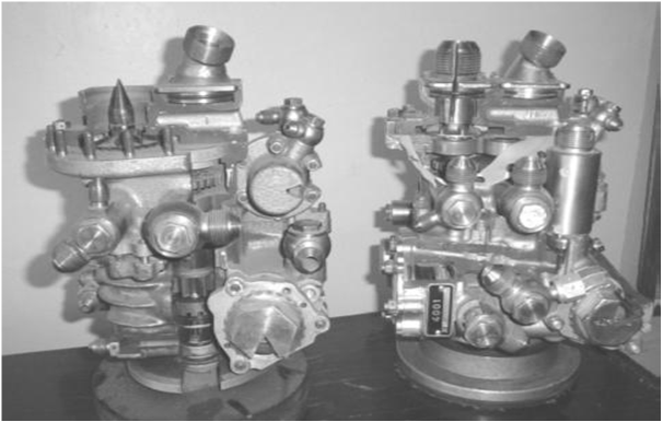
Fig. 1. Gear pumps fuel-supply system of aircraft engines AI-25 and AI-25T: 1 - unit, 2 - unit, 3 - pairfriction "ends of gear teeth - saddle."
As a result, the main reasons of the unit’s failure according to the given criterion were discovered (tab., fig. 2-5).
Three last types of the units failures are directly connected with operating conditions of the "gear teeth ends – end thrust bearing" friction pair and reach about 45% of all types of failures, which is in good agreement with other literary sources [2, 3, 4].
Usually, for aviation units, the high accuracy in production of the components, the feature-based precision and strength control meet all necessary requirements; and the system of acceptance tests and a trial run of assembled units show their compliance with output passport specifications; further on the units are operated in comparable conditions.
The main reason of the early failures is the actual loaded condition of the unit, which mainly depends on design features and its actual relative position of the assembled unit components, i.e. the combination of its manufacturing and installation errors. The assessment of a relative position of gear pump assembled components was realized by means of probability vector representation of manufacturing and installation errors. [5, 6].
Table 1- The main types of aviation gear pump failures and their reasons (units )
|
Type of unit’s failure |
Identified cause of failure |
|
1. Unit's failure due to the following defect: "Fuel pressure disturbance in the engine" (failures share – 46,7% of total quantity of failures)
2. Unit's failure due to the following defect: "Misfire" (failures share – 18,3 %) 3. Unit's failure due to the following defect: "Cutting waste in the filter" (failures share – 11,7 %) 4. Unit's failure due to the following defect: "Engine speed loss and it's stop" Failures share – 15 %) |
The reason is a heavy increase in volume losses of power fluid from a discharge chamber into an inlet chamber of the pump through a field due to opening of contacts of operating profiles of gear teeth. This provokes a dynamic load increase at gear teeth and growing of contact stresses, resulting in increased wear of gear teeth of the pump (fig. 2). The reason is growing of volume losses of power fluid in gear pump pockets and falling of its volume efficiency. Thus the pump disassembly shows an increased wear of surfaces of end thrust bearing mechanical seals of the gear pump (fig. 3). The wear of gear teeth (fig. 1), end thrust bearings and bearing assembly (fig. 4). The reason is the loss of strength of the leading gear spindle , caused by its fatigue failure (fig. 5).
|
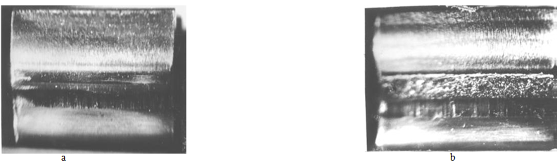
Fig. 2. Wear of gear teeth pump: A - on the head of a tooth, b - by tooth root.
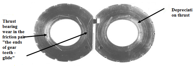
Fig. 3. Gear pump thrust bearing wear
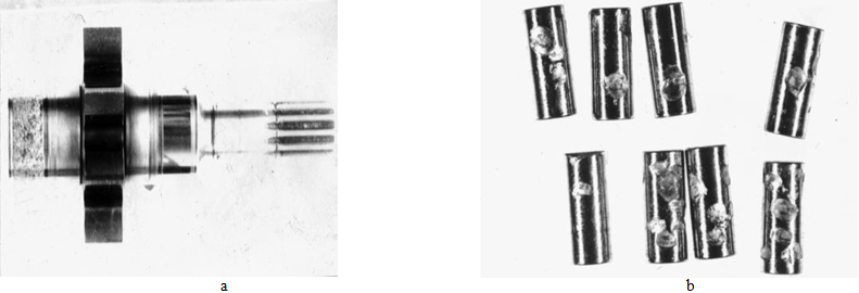 Fig. 4. Wear in the bearing assembly of pump: a - pin drive gear, b - roller bearing assembly.
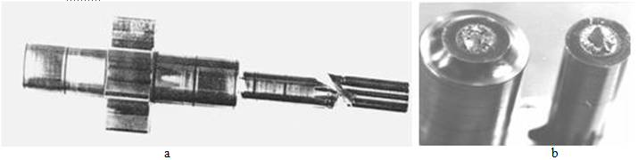
Fig. 5. The cut pinion shaft pump: a - the groove slots, b - on the fillet.
Considering that the pinions position of the pump is governing in its design, in the paper inaccuracy of their positions in probability vector concept was estimated, which for units considered, reaches on the angle of an assembly distortion of gear teeth ends relative to a friction surface with the end thrust bearing makes  from 0 to
  radians (fig. 6) .
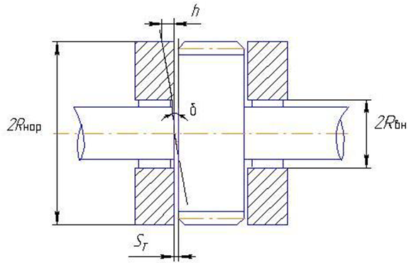
Fig. 6. Design model of the friction pair.
The presence of end thrust bearings which are mechanical seals of the gear pump, are structurally strictly oriented on gear teeth ends and prevent from a gear turn on the assembly distortion angle, δi and, as a result, additional axial efforts exerting on the surface of thrust bearings arise.
The value of the additional axial effort to end thrust bearings depends on the value of a received "rapprochement" of gear teeth end surfaces and end thrust bearings:  (fig. 6), where h – a maximum value of the penetration of gear teeth ends into the end thrust bearing; δ – a gear distortion regarding to the thrust bearing, due to assembly errors; r – a maximum distance from a gear axis to the line of action of the axial effort arisen; sт –a value of the end gap between gear teeth ends and the end surface of the end thrust bearing.
sт end gaps between gear teeth and the end thrust bearing aren't constants, but are periodically replaced due to gear ends outrun, nonparallelism and roughness of adjoining gear surfaces and the end thrust bearing, elastic distortion of sliding surfaces in contact zones, etc. That is why the value of sт end gap is above the minimal acceptable value  microns, as a rule, and varies due to the gear angle of rotation within 5-15 microns.
Let's analyse the gear curving effect onto the loaded condition in "gear teeth ends – end thrust bearing" friction pair with the help of frictional fatigue theory approaches. The techniques used for this purpose, were presented in publications [7, 8] for example.
Necessary basic data according to dimension tolerance of the details' sizes, constructive, technical, materials research characteristics of gear teeth wear surfaces and the end thrust bearing of units, materials and their processing technology are taken from design and technological documentation on units, as well as from literary sources. The allowances in calculations were accepted according to the recommendations, given in the specified literary sources, namely:
1. "Gear teeth ends – end thrust bearing" friction pair wear happens in a stationary (steady) mode under conditions of boundary lubrication, i.e. the thickness of lubricant film doesn't influence the value of normal tension in wear surface zones of the actual contact and the value of their approach .
2. The temperature effect is ignored, i.e. there is a uniform temperature field on the contact surface.
3. Calculating the contour area of a friction pair contact the undulation of their surfaces was ignored, due to precise processing of the gear teeth ends surfaces and the end thrust bearing (grinding-in, abrasion) and their comparatively small sizes 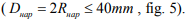
4. Wearing body (end thrust bearing) is smooth and deformable; abrading (implemented) body (gear teeth ends) is rough.
Microroughnesses of the implemented body are presented in the form of spherical segments of a constant radius and density, owning elastic properties, and have a rigid foundation. The tops of microroughnesses are spaced on the height in such a way that the initial part of a basic surface curve is described by the equation:  , where –
  the value of relative approach; b and ν – parameters of the curve basic surface of the rough body, constant for the certain processing type.
5. The type of wear is fatigue. Calculating the wear, it is accepted that roughness parameters are related to the abrading (implemented) body (gear teeth ends), and materials research parameters - to the wearing body (end thrust bearing)
6. The work of friction pair proceeds in the conditions of the external friction.
As a result the assessment of normal loadings of the "gear teeth ends – end thrust bearing" friction pair was made. The received results were used for the assessment of the friction pair fatigue wear.  endurance assessment of the friction pair is given in fig. 7. 1–6 curves show the friction pair endurance depending on the angle of the assembly distortion of gears δ for the recommended value of the end gap between sт wearing surfaces (1- 9 microns, consequently). The symbol ■ – is the minimum possible angle of distortion
  , realized during pump assembly. The symbol ♦ – is the most probable value of the distortion angle
  , realized during pump assembly with probability of
  . The symbol ▲– is the maximum possible angle of a distortion
  , realized during pump assembly.
The calculations showed that at bearable assembly values of the angles of distortion  the increased wear of the end thrust bearing can be observed, and the endurance of "gear teeth ends – end thrust bearing" friction pair can be less than the pump resource is intended, which is observed in practice.
According to well-known techniques, given in [7], the assessment of the moment of friction  acting between gear teeth end surfaces and end thrust bearing was made. The calculations showed that the moments of friction operating in couple can reach inadmissibly high values
  , and they considerably exceed the value of the maximum twist, transferred by the pinion gear shaft of the pump
 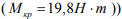 even in the admissible range of assembly errors of the pump for distortion angles δ of gear teeth ends regarding to the end thrust bearing.
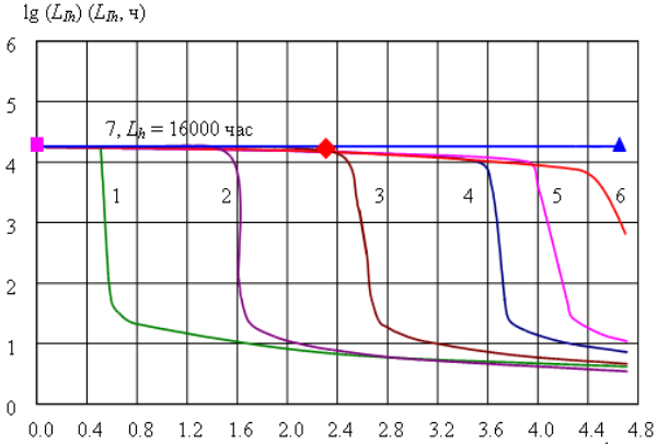
Fig. 7. The estimated life of the friction pair "the ends of gear teeth - axial bearing"
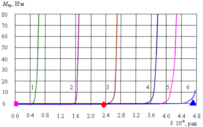
Fig. 8. Calculated friction torque in a pair of "butts of gear teeth-axial bearing"
As a result pump gears become periodically jammed and as the pump motor is driven by a large supply of power from the aviation engine transmission gear box, a fatigue loss of durability of the pinion gear shaft occurs.
The received results well explain the reason of the considered types of failures of the fuel-delivery system gear pumps of engines aviation.
Thus, on the basis of the analysis of the actual loaded condition of details and gear pumps joints, the reasons of standard causes of failure were identified, allowing make a general forecast of its operational life. The quantitative assessment of the actual loaded state of the components allowed explain the reason of life dispersion of the gear pumps of fuel-delivery system of units engines up to 8-10 times.
References
Aistov I.P. Control and diagnostics system of a technical condition of gear pumps of fuel-delivery system of aviation engines /I.P. Aistov, L.O. Shtripling//Automation and advanced technologies: Materials of the fifth intersectoral scientific and technical conference (September 26-28, 2007), Vol. 1. – Novouralsk: NSTU publisher, 2007. – P. 9-12.
Bashurov B. P. Mathematical model selection of preplanning of no-failure operation of volumetric pumps on the correlation analysis basis / B. P. Bashurov. // News of higher education institutions. Mechanical engineering. – 1990 . – No. 7. – P. 56-59.
Braun E.D. Process simulation of abrasion wear of gear pumps precision pairs / E.D. Braun, V.N. Labushina. // Mechanical engineering and automatic equipment problems. – 1991 . – No. 5. – P. 73-79.
Korablev A.N. Development mechanism and reasons of some failures of gear pumps / A.N. Korablev, K.A. Krylov//Issues of reliability increase and endurance of details and joints of the aircraft equipment. – Iss. 1 . – M: Mechanical engineering, 1969. – P. 127-132.
Aistov I.P Quality maintenance of gear pumps assemblage / I.P. Aistov //Assembage in mechanical engineering, tool engineering. – 2006 . – No. 1. – P. 42-47.
Aistov I.P Quality improvement of gear pumps assemblage due to kinematic control implementation / I.P. Aistov // Assembage in mechanical engineering, tool engineering. – 2006 . – No. 8. – P. 30-32.
Kragelsky I.V. Machines friction units: Reference guide / I.V. Kragelsky, N. M. Mikhin. – M: mechanical engineering, 1984. – 280 p.
Triboengineering reference guide: 3 volumes. // Under M. Hebda and A.V.Chichinadze general editorship. – Vol. 1. Theoretical basics. – M: Mechanical engineering, 1989. – 400 p.