Development of control schemes for basic cryptographic transformation operations performed by a programmable logic integrated circuit
Development of control schemes for basic cryptographic transformation operations performed by a programmable logic integrated circuit
Abstract
This article discusses the procedure for developing control schemes for the basic operations of cryptographic transformation of information performed by a programmable logic integrated circuit that is part of the control system of an autonomous technical means. The purpose of the research is to analyze the basic logical operations used by various algorithms for cryptographic transformation of information, as well as to develop a mathematical apparatus for monitoring the correctness of these operations. The control of the execution of logical operations is carried out inside a programmable logic integrated circuit in parallel with the main algorithm of cryptographic transformation of information. In the future, the developed control schemes can be used in the development of an algorithm for technical diagnostics of programmable logic integrated circuits with localization of the location and cause of the malfunction.
1. Introduction
Cryptographic transformation of information (hereinafter referred to as KPI) is the process of changing information that depends on the parameter being changed, and has the property that it is impossible to restore the original information from the transformed one, without knowing the current key, with a labor intensity less than the specified one.
Currently, KPI is implemented by software, hardware, and software-to-hardware tools. At the same time, in the case of even a minimal error of one bit, the information recovery process becomes impossible.
Especially relevant is the problem of error occurrence during KPI on autonomous technical means (hereinafter referred to as PBX) that operate at a long distance from the technical operator and transmit cryptographically transformed information to the processing object via radio channels.
In this regard, there is a need for autonomous monitoring of the implementation of KPI on the PBX in order to determine the error in advance and, if possible, eliminate the malfunction of the device that performs KPI.
The main computing device that performs KPI is currently a programmable logic integrated circuit. This computing tool is the most versatile for implementing various KPI algorithms.
The most cryptographic algorithms are based on four basic logical operations:
– modulo 2 addition operation.
– modulo 2^16 addition operation;
– cyclic shift operation.
– substitution operation.
Control of these logical operations will allow you to most fully determine the technical condition of the FPGA performed by the KPI on the PBX.
Consider numerical control of arithmetic operations modulo. The construction of control schemes is based on two theorems .
Theorem 1. The sum of numbers is comparable modulo q with the sum of the residuals r of the same numbers, i.e.
Theorem 2. The product of numbers is comparable modulo q with the product of the residuals r of the same numbers, i.e.
Let us consider control schemes for the following transformations: summation modulo 2, summation modulo 216, substitution and cyclic shift operation
, , .2. Results and Discussion
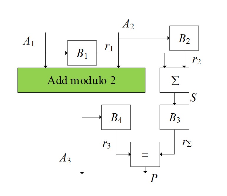
Development of an algorithm for controlling the modulo summation operation. The control scheme for adding numbers modulo 2 is shown in Fig. 1.

Figure 1 - Control of the value of binary numbers modulo 2
The result of summing two numbers А1 and A2 is the number А3. In blocks B1 and B2, the residuals r1 and r2 numbers A1 and A2 before conversion, respectively. Then, in block S, the resulting residuals are summed up. Since the sum of the residuals can be greater than the modulus, then at the output of the adder, it is necessary to perform the operation of finding the remainder again using the conversion in block B3. As a result, the remainder rA3 obtained from the number A3 is compared with the sum of the remainder of the numbers А1 and A2 – in the comparison module (≡) with the formation of the "norm" sign (P) in the form of a logical unit and zero – otherwise. It should be noted that the P-value is an additional feature (parameter) of the subsystem functioning and diagnostics model, i.e.
The functioning of the presented control scheme can be divided into several stages:
1. At the initial stage, the numbers involved in the addition operation modulo 2 are obtained. After that, the remainder of the terms r1, r2 and their sum (S = r1 + r2) are found.
2. In the next step, we determine the remainder r3 of the sum of the residuals S and the remainder r4 of the sum of the terms А1 and A2.
3. At the last stage, a report is generated about whether the summation is correct (output Р1) or not (output Р2).
From a formal point of view, these stages can be represented as a set of the following maps
:where B1 is an operator that characterizes getting the remainder r1 from a number A1.
where B2 is an operator that characterizes getting the remainder r2 from a number A2.
where S is the operator for finding the sum of balances r1 and r2.
where B3 is an operator that characterizes obtaining the remainder r3 from the sum of the remainder r1 and r2.
where P is an operator that characterizes obtaining the solution p.
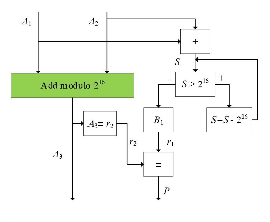
When controlling addition modulo 2^16, the scheme is simplified, taking into account the fact that the remainder of two numbers is calculated in the transformation itself (Fig. 2).

Figure 2 - Control of the position of binary numbers modulo 2^16
1. At the initial stage, the addition of numbers is performed. After that, the sum is compared with the number 2^16. If the value is exceeded, the difference is calculated
2. In the next step, we define the remainder r1 of the sum of the numbers S and the remainder r2 as a number A3 (A3 ≡ r2).
3. At the last stage, a report is generated about whether the summation is correct (output Р1) or not (output Р2).
Basic analytical relations
:where B1 is an operator that characterizes getting the remainder r1 from a number S.
where P is an operator that characterizes obtaining the solution p.
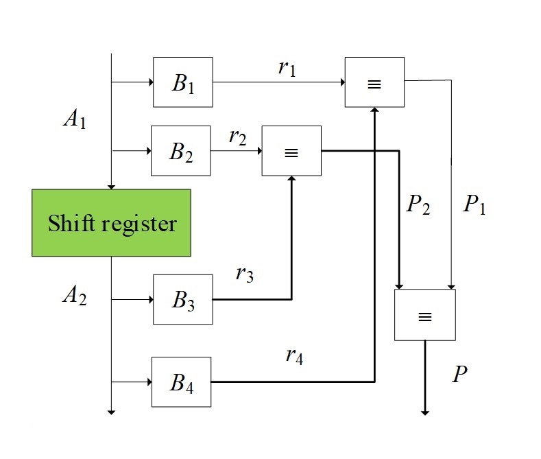
The control scheme of the shift operation is shown in Fig. 3.

Figure 3 - Control scheme for the shift operation
1. At the initial stage, the number is represented A1 as two numbers relative to the number of clock cycles of the shift towards the highest digit. The residuals of the indicated numbers are calculated. Similarly, the component numbers are determined A2 and the residuals are calculated.
2. In the next step, the remainder of the numbers before and after the shift is compared.
3. At the last stage, a report is generated about whether or not the number shift (P) is correct.
Basic analytical relations
, :where B1, B2 are operators that characterize obtaining residuals r1 and r2 from a number A1.
where B3, B4 are operators that characterize obtaining residuals r3 and r4 from a number A2.
Comparing numbers before and after the shift
where P1, P2 are the results of comparing the residuals r3 and r4.
where P is an operator that characterizes obtaining the solution p.
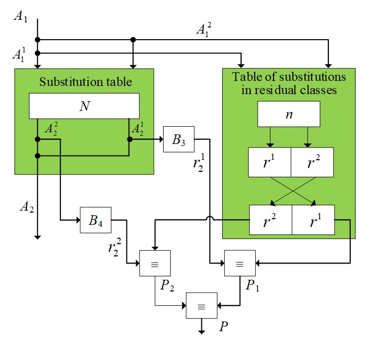
The control scheme for substitution operations is shown in Figure 4.

Figure 4 - Control scheme for the substitution operation
The functioning of the presented control scheme can be divided into several stages:
1. At the initial stage, the division of the numbers A1 and A2 by the corresponding numbers is carried out, and the definition of the numbers and
.
2. From the table of residuals n, select the residuals r1 and r2.
3. The remainder ( and
) of the numbers are generated after performing the substitution operation and compared with the remainder from the remainder table.
4. At the last stage, a report is generated about whether the substitution is correct or not (P).
Basic analytical relations
:where B3 is an operator that characterizes getting the remainder from a number
.
where B4 is an operator that characterizes getting the remainder from a number
.
Comparing numbers before and after the shift
where P1, P2 are the results of comparing the residuals and
.
where P is an operator that characterizes obtaining the solution p.
3. Conclusion
Thus, we have developed control schemes for the main operations of cryptographic transformation, namely addition modulo 2,modulo 2 ^ 16, shift and substitution. Many additional parameters of the technical diagnostics process have been formed. It is necessary to make adjustments to the functioning model of the encoder, taking into account the process of its technical diagnostics, based on the obtained parameters.
