Return to article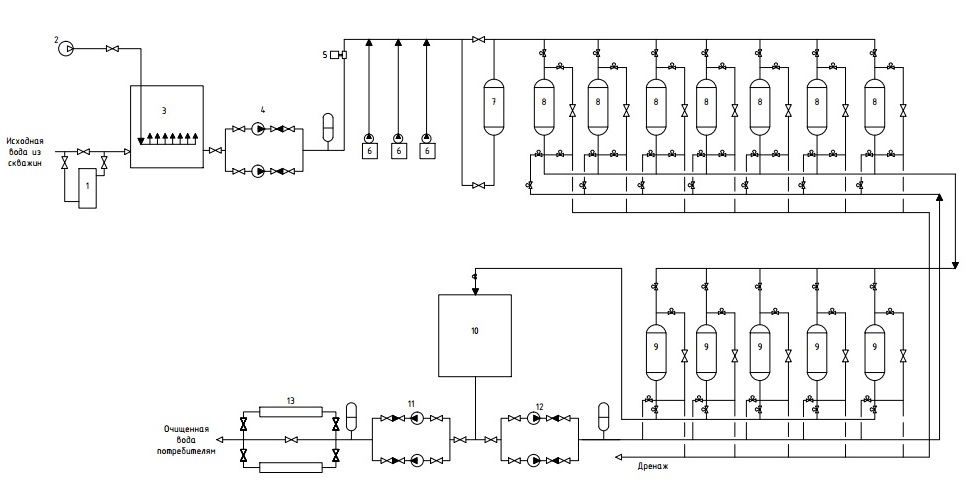
ИНТЕНСИФИКАЦИЯ ПРОЦЕССОВ ВОДОПОДГОТОВКИ ПОДЗЕМНЫХ ВОД ДЛЯ НЕФТЕПЕРЕРАБАТЫВАЮЩИХ ПРЕДПРИЯТИЙ ВЫСОКОШИРОТНЫХ ТЕРРИТОРИЙ
Figure 1 - Basic instrumental and technological diagram of a water treatment plant
1 – heat exchanger; 2 – oil-free compressor; 3 – aerator; 4 – pumping station of the second rise; 5 – electromagnetic flowmeter; 6 – dosing complexes; 7 – contact chamber; 8 – clarifying filters with electric shutters; 9 – sorption filters with electric shutters; 10 – a reservoir of clean water; 11 – pumping station of the third lift with a frequency converter; 12 – pumping station; 13 – ultraviolet lamps