Методика гармонического анализа окружной неравномерности потока пара за поворотной диафрагмой турбины
Методика гармонического анализа окружной неравномерности потока пара за поворотной диафрагмой турбины
Аннотация
Рассмотрена регулирующая ступень с поворотной диафрагмой на теплофикационном отборе паровой турбины. Разработана методика построения 3D-модели регулирующей диафрагмы ступени турбины для её дальнейшего исследования. Методами численного эксперимента исследована неравномерность поля скоростей за сопловым аппаратом рассмотренной ступени турбины. Разработанная методика апробирована на различных режимах работы поворотной диафрагмы. Установлено, что для рассмотренной ступени динамическая составляющая окружной неравномерности потока перед рабочими лопатками значительно превышала динамическую составляющую неравномерности потока по высоте лопаток. Отмечен значительный размах пульсаций скорости, достигающий 200…250 м/с при максимальной скорости пара 455 м/с. Проведен спектральный анализ полученного поля скоростей, позволивший определить потенциально опасные частоты пульсации парового усилия. Выполнено сопоставление частот пульсации парового потока с собственными частотами лопаток рабочего колеса турбины, найдены условия возникновения резонанса. Это делает возможным поиск и определение возможных опасных частот переменной аэродинамической силы, действующих на рабочие лопатки ступени с поворотной диафрагмой, от совмещения спектра частот гармоник окружной неравномерности потока и спектра собственных частот колебаний лопаток (пакета лопаток, всего венца лопаток) на различных режимах работы турбины.
1. Introduction
The reliability of the steam turbine plant is largely determined by the accident-free operation of the turbine, which, first of all, depends on the reliability of the operation of its blade apparatus, as well as its regulators – valves and rotary diaphragms
, , , . Rotor blades of steam turbines are one of the most loaded elements of the turbomachine design. Numerous cases of emergency destruction of blades are known, which led to complete failure of the entire turbine plant , . The reasons leading to the destruction of the blades are diverse: from errors in their design and manufacture, to the impossibility of complete quality control of structural materials, as well as erosion wear and operation in non-design modes. One of the most important parameters that determine the dynamic strength of the blades and the fatigue stresses in them are the values and frequencies of disturbing forces acting on the side of the incoming flow onto the blades. The frequencies of these forces are always a multiple of the rotor speed of the turbine, but its harmonic composition significantly depends on the design of the flow path both before and after the blades in question. The most dangerous, in terms of resonant phenomena of the blade apparatus, are frequencies up to the 6th harmonic of the natural frequency of the blades inclusive. However, modern data indicate a danger and higher frequency harmonics, up to 8-9 . Thus, harmonic analysis of the dependence of the disturbance force on the circumferential unevenness of the flow acting on the blades is an extremely important task.In the design of many steam turbines with adjustable steam extraction, control stages with rotary diaphragms are provided. Before the rotor blades of such stages, an uneven flow of steam is formed along the circumference, the characteristics of which depend both on the design of a particular diaphragm and on the mode of its operation, that is, the degree of its opening. Analytically, it is not possible to obtain characteristics of such unevenness, due to the complex spatial nature of the current. It is proposed to solve this problem by numerical modeling
according to the methodology presented below.One of the main objectives of simulation of aerodynamic processes in the rotary diaphragm and nozzle grating of the control stage is harmonic analysis
of flow heterogeneity in the gap between the nozzle and working grating in order to obtain the frequency spectrum of harmonics of the disturbing force acting from the flow side on the rotor blades during turbine operation.2. Research methods and principles
When implementing the proposed procedure, a control stage with a rotary diaphragm was considered at the heat extraction of the steam power turbine of the steam-gas plant
. Modeling was carried out using a three-dimensional model of the system: rotary diaphragm – intermediate chambers with partitions – nozzle grating. For the convenience of modeling and evaluating the results, this model is converted into a flat pattern by the average diameter of this turbine stage. For the flow sections of the reaming of the fixed and rotary ring of the diaphragm, the equality of the sections of the nozzle guide vanes and the meridional section of the diaphragm model was maintained.The model created by the authors is shown in Figure 1; it allows you to obtain any degree of opening of the rotary diaphragm by moving the scan of the model of the rotary ring of the diaphragm relative to the scan of the stationary ring.
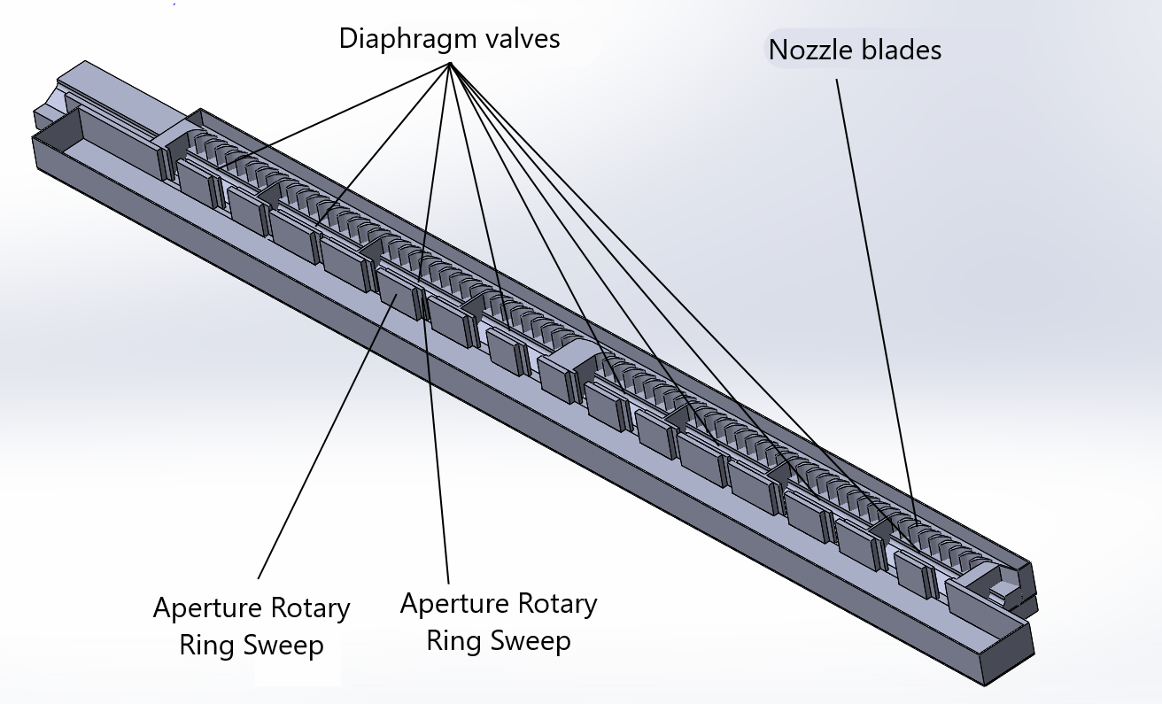
Figure 1 - System model: rotary diaphragm - intermediate chambers with partitions - nozzle grating
The mathematical model of the flow of compressible viscous gas (water vapor) was based on a system of classical equations for preserving mass, momentum and energy. The k-e model
was used as a turbulence model.A calculated grid was built in the volume of the design model. To increase the accuracy of modeling, it was adapted – local grinding in critical areas of the calculated area – in the area of models of aperture windows, internal volume of cavities, inter-blade channels of the nozzle assembly.
Figure 2 shows a fragment of the calculated grid of the calculated region of the model. The total number of calculated cells in the entire simulated region is more than 8 million.
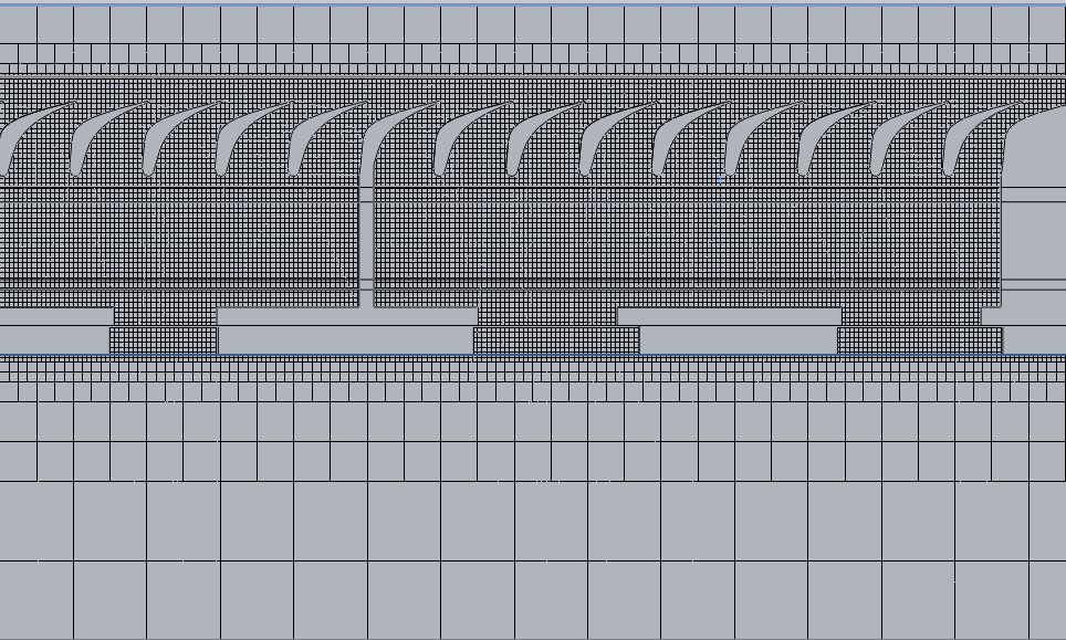
Figure 2 - Fragment of the calculated grid
3. Main results
The condensation mode of the turbine
provides for the complete opening of the windows of the rotary diaphragm. Results of steam flow simulation in condensation mode are shown in Figures 3 and 4.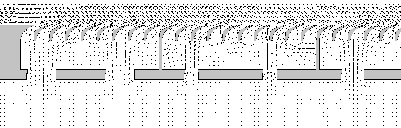
Figure 3 - Vapor velocity vectors on the characteristic portion of the diaphragm when the diaphragm is fully opened on the middle diameter
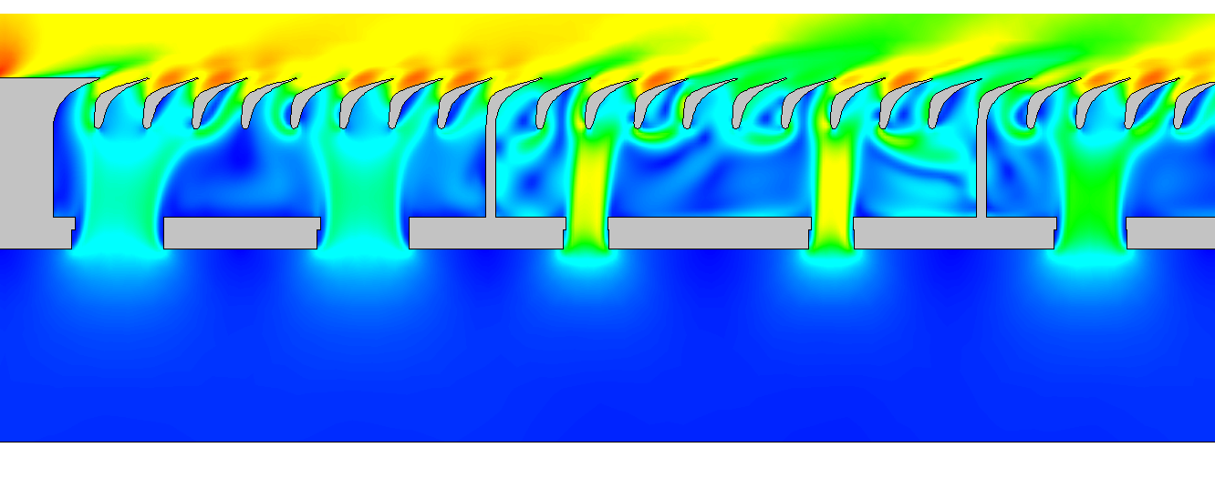
Figure 4 - The steam velocity field in the characteristic section when the diaphragm is fully opened at the middle diameter of the control stage
It can be seen from Figures 3, 4 and 5 that the steam exiting through the windows of the rotary diaphragm forms a non-uniform flow in the diaphragm cavities. Steam flow rate in nozzle channels within each cavity is different. Most of the steam, in this mode, passes through nozzle channels located opposite the open windows of the rotary diaphragm.
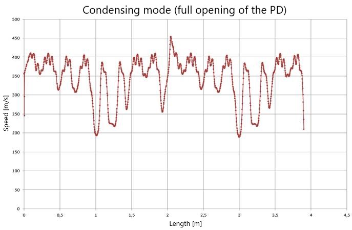
Figure 5 - Change in the steam velocity at the inlet to the working grid when the diaphragm is fully opened along the circumference on the middle diameter of the stage
Steam speed pulsations in front of the rotor blades, in the considered mode, at each rotation of the rotor have a significant span reaching 200... 250 m/s with a maximum steam speed of 455 m/s. These velocity pulsations form significant steam force pulsations on the rotor blades.
In order to determine the potentially hazardous frequencies of steam force pulsation, the spectral analysis of the dependence presented in Figure 5 was carried out. The results of spectral analysis of the circumferential irregularity of the steam flow upstream of the blades in condensation mode are shown in Figure 6. It is obtained that harmonics with the highest amplitudes are multiples of 100 Hz, while the maximum amplitude has harmonics of 800 Hz and 100 Hz.
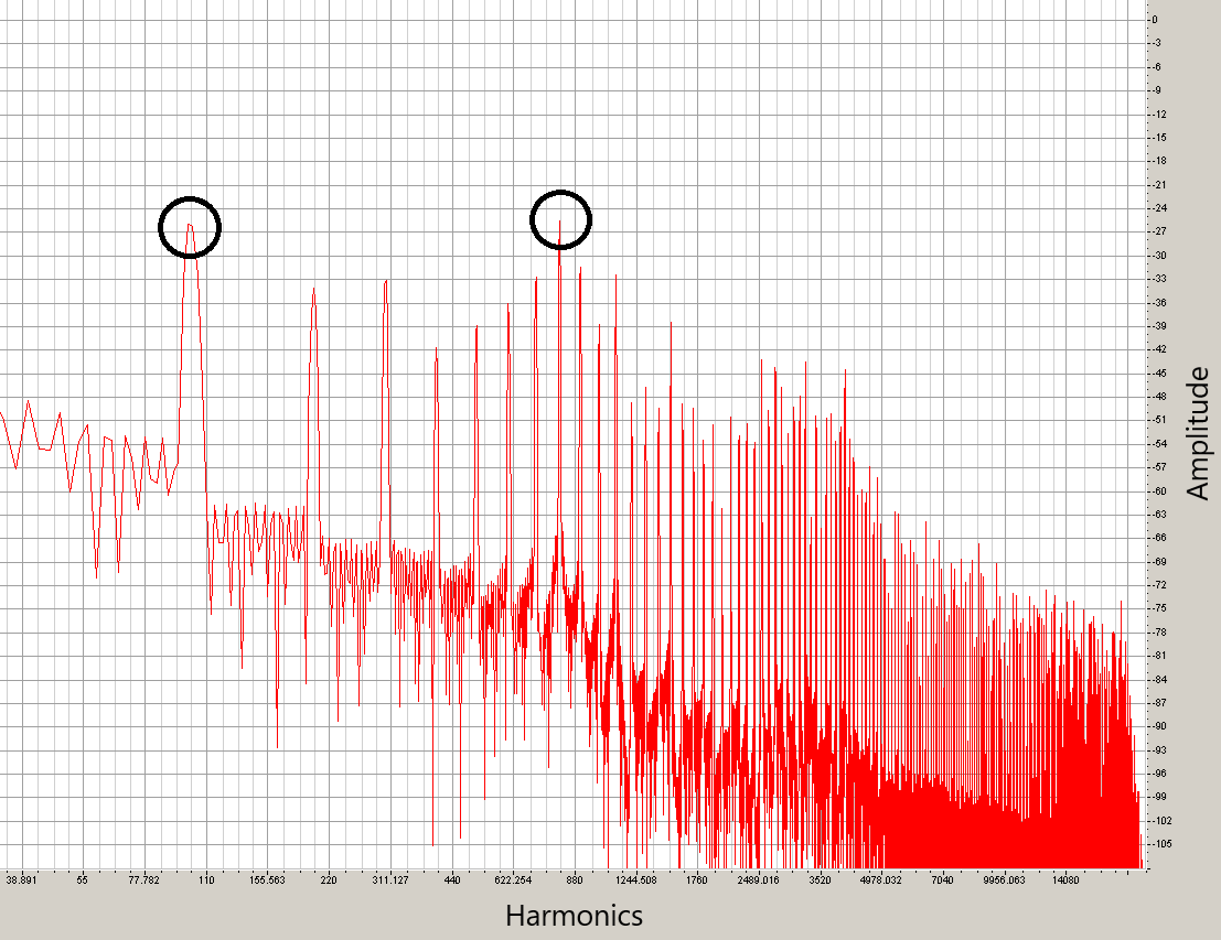
Figure 6 - Results of spectral analysis of circumferential irregularity of steam flow upstream of rotor blades in condensation mode:
circles - largest amplitude
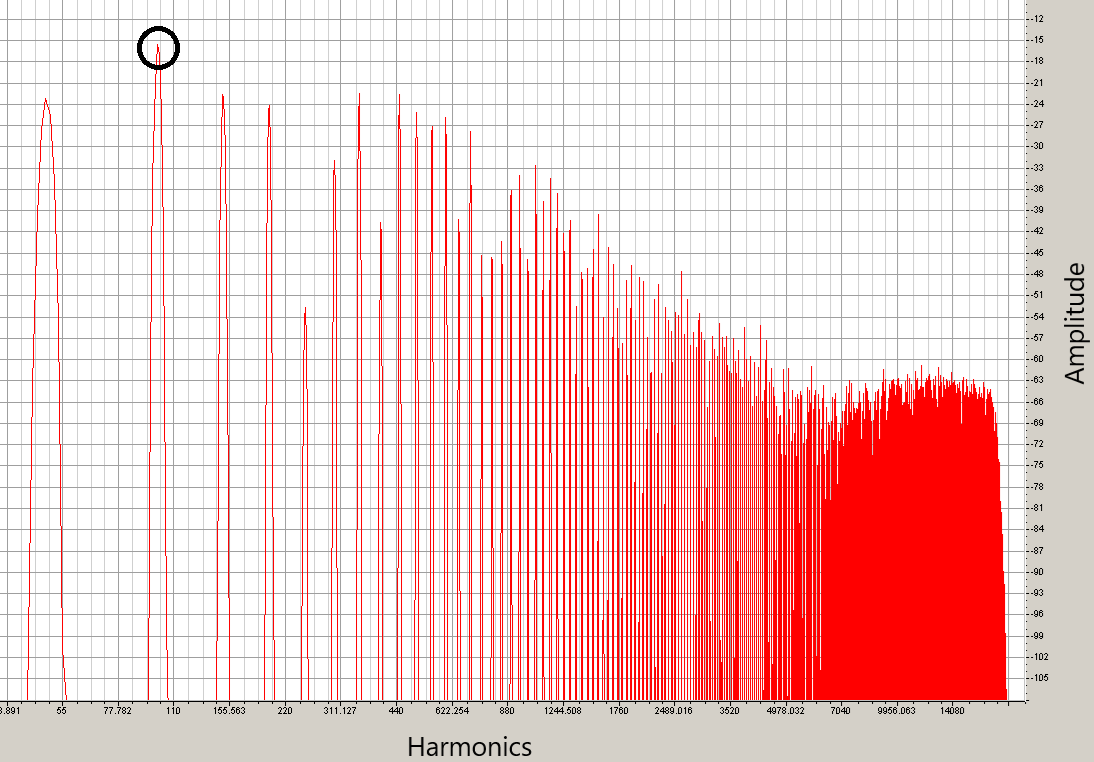
Figure 7 - Results of spectral analysis of circumferential irregularity of steam flow upstream of rotor blades at heating mode:
circle - largest amplitude
4. Discussion
The variable field of flow rates in the circumferential direction at the outlet of the nozzle assembly is the cause of pulsation of the aerodynamic force (steam force) acting on the rotor blades of the turbine stage in question. This, in turn, leads to the emergence of alternating stresses that affect the strength characteristics of the rotor blades.
The coincidence of harmonic frequencies with the maximum amplitude of this force with the natural frequencies of the blade rim is especially dangerous, while resonant phenomena and destruction of the blades are possible
.Natural frequencies and forms of vibrations of rotor blades (blade stack, the whole blade rim of the considered stage) were also determined by numerical methods in specialized software. Harmonics up to and including 9 were considered potentially dangerous.
It is almost impossible to accurately determine the magnitude and direction of the variable aerodynamic force acting on each rotor blade. This requires the calculation of the unsteady process of steam flow in the flow part and detailed modeling of tear currents, both in the diaphragm and within the nozzle and working grids, but it is known that the harmonics of non-uniformity of steam flow and aerodynamic forces are connected by linear dependence and have the same frequency
.The value of the variable aerodynamic force itself is not determining, it is much more important that its main frequencies (harmonic frequencies with maximum amplitude) do not coincide with the resonant frequencies of the elements of the flow path.
5. Conclusion
Thus, one of the goals obtained using the proposed technique is to find and determine possible dangerous frequencies of variable aerodynamic force acting on the rotor blades of the stage with a rotary diaphragm from the combination of the frequency spectrum of harmonics of the circumferential unevenness of the flow and the spectrum of natural frequencies of vibrations of the blades (a set of blades, the entire rim of the blades) in various modes of turbine operation.
A technique has been developed to determine the potentially dangerous frequencies of the variable aerodynamic force generated in front of the operating grid of the control stage with the rotary diaphragm in various modes of its operation.
The study, using the proposed method, of various operating modes of the rotary diaphragm, allows the obtained potentially dangerous frequencies for each operating mode, to be compared with the natural frequencies of the working rim of the control stage, and, in case of coincidence of these frequencies, either change the design and configuration of the windows of the rotary diaphragm, or structurally rebuild the blade apparatus from dangerous frequencies, or prevent such dangerous modes during turbine operation.
From all of the above, it can be concluded that the application of the procedure described in the article makes it possible to significantly improve the process of designing the turbine flow path.