
Алгоритмы искусственного интеллекта для тяжелых беспилотных воздушных судов
Алгоритмы искусственного интеллекта для тяжелых беспилотных воздушных судов

Аннотация
Современная жизнь уже немыслима без UAV`s. Основным препятствием более широкого применения является энергетический фактор — запас энергии в аккумуляторах и ее эффективное расходование. Большие средства тратятся на поиск новых источников энергии, разработке новых месторождений лития и улучшение конструкций аккумуляторов. Но значительно меньше внимания уделяется электронным распределительным устройствам этой энергии (ESC регуляторы, коммутаторы, алгоритмы управления и работы).
Эту ситуацию можно сравнить с переходом автомобильной промышленности от карбюраторов к электронным системам впрыска топлива, что позволило значительно повысить топливную эффективность. С появлением в нашей жизни Искусственного Интеллекта (ИИ) стало возможным значительно повысить эффективность данных устройств и обеспечить значительный прирост автономной работы UAV`s.
В данной статье приведены некоторые примеры алгоритмов для управления тяжелого транспортного мультикоптера, позволяющие значительно увеличить время его полета без использования дополнительных аккумуляторов и повышения полетного веса. Хотя рассмотрены алгоритмы управления тяжелым транспортным мультикоптером, многие описанные алгоритмы могут быть успешно использованы и в других типах UAV`s для экономии энергии аккумуляторов и повышения времени автономной работы. Особо следует отметить, что даже использование электронных коммутаторов со стандартными ESC-регуляторами позволяет увеличить время автономной работы UAV`s до 30%.
1. Introduction
A standard BLDC (Brushless DC) system consists of a battery, an ESC (Electronic Speed Controller), and a BLDC motor , , , , as shown in Figure 1.
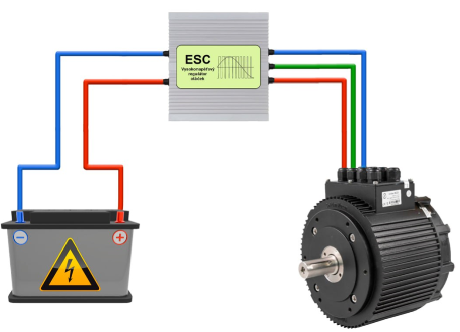
Standard BLDC system
Recent advancements have introduced Lithium Titanate (LTO) , , batteries have been introduced for use in heavy UAVs. Their key advantages include extremely fast charging–an important feature for aerial taxi applications–and reliable operation at low temperatures. However, all battery types share a common trait: a nonlinear discharge profile. This characteristic must be taken into account to ensure reliable UAV performance , .
The ESCs convert the energy stored in the battery into high-frequency pulses to drive BLDC motors , . Most ESCs share a similar circuit architecture comprising of a microcontroller and high-power MOSFET transistors , , with variations in synchronization algorithms, PWM frequency, and the power handling capacity of the output stage . Silicon-based MOSFETs are used as power switches in nearly all ESCs , , . However, there are already small-batch ESCs based on GaN (Gallium Nitride) transistors , , , , which outperform silicon-based designs and allow high-power, compact solutions. Their main drawback is high cost and the need for liquid cooling.
BLDC motors themselves follow a consistent design principle, differing mainly in size, number of poles, and magnet configurations . Most motor windings are made from copper wire with enamel insulation rated for up to 130 °C , , while newer implementations employ nickel-plated copper wire with high-temperature insulation rated up to 300 °C , . This enables operation of windings at temperatures up to 250°C, supporting current levels exceeding standard limits , preventing insulation breakdown during prolonged peak load conditions, and enabling short-term “boost” modes . Additional thermal protection for rotor magnets is achieved through specialized heat-resistant coatings and barrier layers , , .
Furthermore, the use of ceramic ball bearings significantly extends motor lifespan, as bearings are the only components subject to mechanical wear in BLDC motors , .
In contrast to small drones, heavy multicopter-type UAVs also incorporate variable-pitch propeller systems. These allow the motor-propeller group to adapt to different loads and flight conditions , . However, in most systems, all propellers are adjusted simultaneously: a higher pitch for light-load high-speed flight, and a lower pitch for heavy-load low-speed flight.
2. Proposed Modernized BLDC System
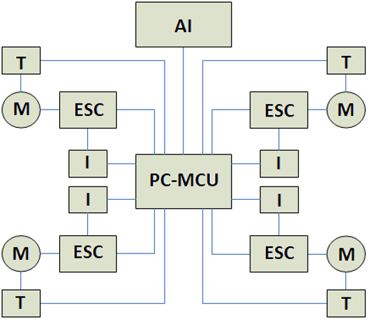
Modernized BLDC System
The flight controller PC-MCU handles real-time UAV navigation and stabilization tasks.
The Artificial Intelligence module (AI) stores data on all system components, including their operating limits and specifications. It also runs algorithms designed to optimize energy consumption during flight by intelligently managing power distribution and motor performance.
The following sections describe several practical AI-based algorithms that have been successfully implemented on a heavy-duty multicopter and have proven effective in real-world testing.
3. Proposed Algorithms, Experimental Verification, and Results
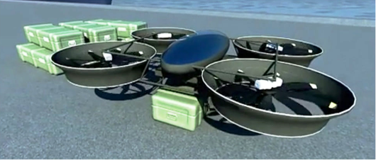
Heavy Transport Multicopter-Type UAV
To transport irregular or oversized loads, heavy multicopters typically use an external suspension system, with the suspension point located at the UAV’s center of gravity. However, this method is not always suitable–for example, during ground-effect flight at low altitudes (below 3 meters) or in strong wind conditions where there is a risk of load swinging. In such cases, proper load distribution on the platform and balancing of the UAV become crucial.
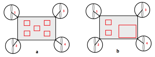
Uniform (a) and non-uniform (b) load distribution on the UAV platform
Furthermore, to maintain balance with uneven cargo placement, motor 4 must operate at significantly higher speeds than the other motors. This results in excessive heat generation, accelerated bearing wear, and a higher current load on its ESC. A component under sustained overload becomes a point of failure, with reduced reliability, shorter lifespan, and higher failure probability. In heavy multicopters, failure of even one of the four motors results in complete failure of the aircraft. Thus, cargo imbalance is a critical factor in UAV operation.
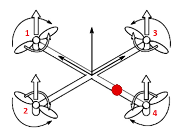
Conceptual UAV
where
CA — thrust coefficient for an ideal propeller;
ρ — air density;
n — propeller rotational speed (RPM);
D — propeller diameter.
To maintain stable flight under asymmetric loading, the thrust produced by motor 4 must be three times that of motor 1. Similarly, motors 2 and 3 must each produce twice the thrust of motor 1.
This leads to the following required speed ratios between motors:
· Motor 1 : 1;
· Motors 2 and 3 : 1.41;
· Motor 4 : 1.73.
For example, if motor 1 is spinning at 5,000 RPM, motor 4 would need to spin at approximately 8,650 RPM while still retain sufficient headroom for maneuvering — which is often not feasible in real-world conditions.
Another critical factor for heavy multicopters is managing centrifugal forces generated by the spinning propellers, which can cause unwanted yaw (rotation about the vertical axis). As a propeller spins, centrifugal force acts outward along the blade, perpendicular to the axis of rotation.
The force on any given point of the blade is proportional to the square of its angular velocity, described by:
where
m — mass of the blade segment;
ω — angular velocity;
r — radial distance from the axis.
If propellers are arranged in counter-rotating pairs (two clockwise, two counterclockwise) and spin at equal speeds, these centrifugal forces cancel out. However, when there are significant differences in RPM — as in this case, where some motors are spinning nearly twice as fast as others — a net rotational torque arises, which the flight controller must counteract. In some situations, the motors may lack the dynamic range to fully compensate, leading to instability.
This is why the platform balancing algorithm is critical not only for flight reliability but also for ensuring precise control.
In our heavy-lift multirotor systems equipped with variable-pitch propellers, this issue is addressed by dynamically adjusting the pitch of each propeller. Based on the load distribution across the platform, the balancing algorithm tunes individual blade pitch values to equalize the average rotational speed of each motor. This helps prevent overloading, extends service life, and ensures stable, energy-efficient operation.
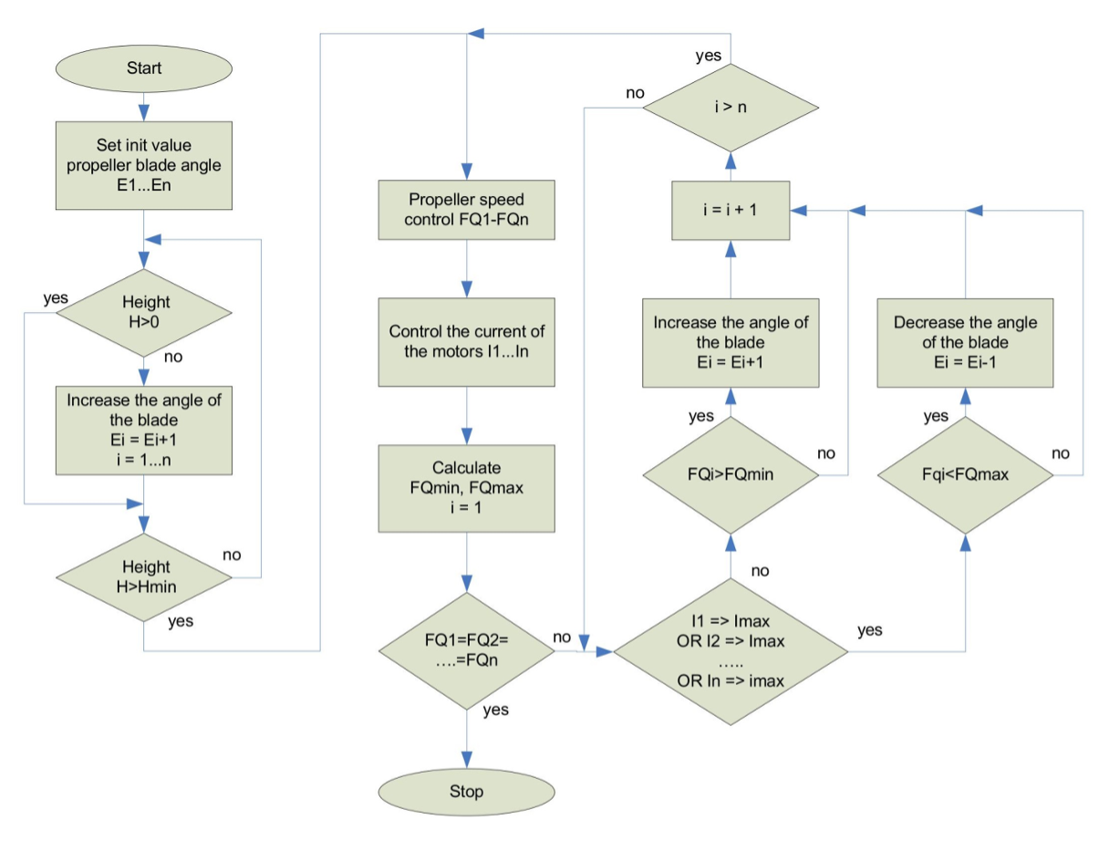
Structural Diagram of the Platform Balancing Algorithm
The system then enters a continuous adjustment phase. It monitors ESC current in real time and makes dynamic pitch and RPM corrections: for arms where motors are spinning faster, the algorithm increases propeller pitch while proportionally reducing RPM. Conversely, for arms with lower RPMs, the pitch is reduced and motor speed increased. This adaptive process ensures all rotors operate at approximately the same average RPM, which helps evenly distribute mechanical wear–particularly on motor bearings.
In addition to the core logic, an AI-based module (not shown in the diagram) continuously monitors several critical parameters to ensure system reliability:
· ESC current on each rotor arm, to prevent exceeding safe peak thresholds;
· Motor temperature, to avoid stator overheating and subsequent rotor magnet demagnetization due to thermal stress;
· Propeller RPM and PWM signal duration to minimize heat buildup during rapid switching transitions in the ESC’s MOSFET output stage.
Based on these inputs, the algorithm continuously adjusts system parameters to meet operational reliability requirements of all critical components. The algorithm was tested on a dedicated bench setup simulating a representative UAV. Measurement results were recorded at two stages:
· Initial stage: Lift to minimum altitude without adjusting motor speed or propeller pitch;
· Final stage: After applying RPM and pitch corrections.
The corresponding data is summarized in Table 1.
Experimental results before and after RPM-based propeller pitch adjustment
| Initial Stage | Final Stage |
Motor 1 RPM | 1800 | 2850 |
Motor 2 RPM | 2800 | 2800 |
Motor 3 RPM | 2800 | 2800 |
Motor 4 RPM | 3450 | 2750 |
Propeller Pitch 1 | 8 | 5 |
Propeller Pitch 2 | 8 | 8 |
Propeller Pitch 3 | 8 | 8 |
Propeller Pitch 4 | 8 | 10 |
The data clearly demonstrates the algorithm’s effectiveness in equalizing rotor RPMs across the platform. The slight deviation in Motor 1's final RPM from the target value occurs because the thrust vector of Motors 2 and 3 does not align perfectly with the platform’s center of gravity, introducing a minor imbalance in overall lift distribution.
From an aerodynamic standpoint, it would be advisable to expand the algorithm with constraints on permissible propeller pitch values to ensure stable and predictable behavior.
Below is a code snippet illustrating the implementation of the described algorithm:
1#define NUMBER_ROTOR                  4
2#define BLADE_ANGLE_START       2
3#define BLADE_ANGLE_MAX                            20
4#define HIGH_TAKEOFF                    2000                            //mm
5#define MAX_CURRENT                     10000                          //mA
6#define DELTA_CURRENT                                   100                             //mA
7#define DELTA_SPEED                        100                              //rpm
8#define MAX_SPEED                            10000                          //rpm
9
10int Blade_Angle[NUMBER_ROTOR];
11
12// Takeoff and weighing
13int Takeoff(void)
14{
15             int Index;
16             int Max_Angle;
17             for(Index = 0; Index < NUMBER_ROTOR; Index++) Blade_Angle[Index] = BLADE_ANGLE_START;
18             Start_ESC();
19             while(Get_High() < HIGH_TAKEOFF)
20             {
21                              for(Index = 0; Index < NUMBER_ROTOR; Index++) Set_Blade_Angle(Blade_Angle[Index]);
22                              delay(100);
23                              Max_Angle = 0;
24                              for(Index = 0; Index < NUMBER_ROTOR; Index++)
25                              {
26                                                Blade_Angle[Index]++;
27                                                if(Blade_Angle[Index] > BLADE_ANGLE_MAX) Max_Angle = 1;
28                              }
29                              if(Max_Angle) break;
30             }
31}
32
33// Speed equalization
34int Speed_Equ(void)
35{
36             int Rotor_Speed[NUMBER_ROTOR];
37             int Rotor_Current[NUMBER_ROTOR];
38             int Max_Speed, Min_Speed, Sub_Speed, Max_Current, Index;
39             int Max_Angle;
40
41             while(TRUE)
42             {
43                              Max_Speed = 0;
44                              Min_Speed = MAX_SPEED;
45                              Sub_Speed = 0;
46                              Max_Current = 0;
47                              for(Index = 0; Index < NUMBER_ROTOR; Index++)
48                              {
49                                                Rotor_Speed[Index] = Read_Speed(Index);
50                                                Rotor_Current[Index] = Read_Current(Index);
51                                                if(Rotor_Speed(Index) > Max_Speed) Max_Speed = Rotor_Speed(Index);
52                                                if(Rotor_Speed(Index) < Min_Speed) Min_Speed = Rotor_Speed(Index);
53                                                if(Rotor_Current(Index) > Max_Current) Max_Current = Rotor_Current(Index);
54                              }
55                              for(Index = 0; Index < NUMBER_ROTOR; Index++) Sub_Speed = Sub_Speed + (Max_Speed - Rotor_Speed(Index));
56                              Sub_Speed = Sub_Speed/NUMBER_ROTOR;
57                              if(Sub_Speed < DELTA_SPEED) break;
58
59                              Max_Angle = 0;
60                              for(Index = 0; Index < NUMBER_ROTOR; Index++)
61                              {
62                                                if(Max_Current < MAX_CURRENT)
63                                                {
64                                                                  if(Rotor_Speed[Index] > Min_Speed) Blade_Angle[Index]++;
65                                                                  if(Blade_Angle[Index] > BLADE_ANGLE_MAX) Max_Angle = 1;
66                                                } else
67                                                {
68                                                                  if(Rotor_Speed[Index] < Max_Speed) Blade_Angle[Index]--;
69                                                                  if(Blade_Angle[Index] < BLADE_ANGLE_START) Max_Angle = 1;
70                                                }
71                              }
72                              if(Max_Angle) break;
73             }
74}
75
76// Current equalization
77int Current_Equ(void)
78{
79             int Rotor_Current[NUMBER_ROTOR];
80             int Max_Current, Index;
81             int Max_Angle;
82
83             while(Get_Stat_ESC())                                // Rotors RUN
84             {
85                              Max_Current = 0;
86                              for(Index = 0; Index < NUMBER_ROTOR; Index++)
87                              {
88                                                Rotor_Current[Index] = Read_Current(Index);
89                                                if(Rotor_Current(Index) > Max_Current) Max_Current = Rotor_Current(Index);
90                                                if((Blade_Angle[Index] >= BLADE_ANGLE_MAX) || (Blade_Angle[Index] <= BLADE_ANGLE_START) Max_Angle = 1;
91                                                else Max_Angle = 0;
92                              }
93                              if(!Max_Angle)
94                              {
95                                                for(Index = 0; Index < NUMBER_ROTOR; Index++)
96                                                {
97                                                                  if((Max_Current < (MAX_CURRENT - DELTA_CURRENT)) Blade_Angle[Index]++;
98                                                                  if((Max_Current > (MAX_CURRENT + DELTA_CURRENT)) Blade_Angle[Index]--;
99                                                }
100                              }
101             }
102}
3.3. Propeller Pitch Optimization Algorithm
This algorithm is used to determine the optimal propeller pitch settings based on the specific conditions of a predefined flight route. As with any navigation system, two modes are available: “Minimum Time to Destination” and “Shortest Distance”.
The “Minimum Time” mode prioritizes the fastest possible travel, aiming for the highest attainable flight speed. Conversely, the “Shortest Distance” mode in this context focuses on minimizing battery energy consumption, operating under an energy-efficient strategy for maximum endurance. The UAV's flight speed depends on propeller pitch, RPM, and is calculated using the simplified formula:
where
s — slip coefficient (typically 0.75);
H — propeller pitch;
n — propeller rotation frequency (RPM).
From this, two derived formulas are used within the algorithm for determining the optimal pitch. To determine the required pitch for a given speed and RPM:
To determine the required RPM for a given speed and pitch:
3.4. Algorithm Overview for Maximum Route Speed Configuration
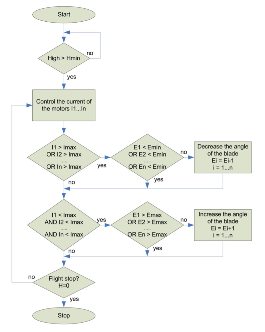
Heavy Transport Multicopter-Type UAV
Subsequently, while continuously monitoring the ESC current in real time, the algorithm gradually increases the pitch of all propellers in sync until one of the following thresholds is reached: either the maximum allowable current on any ESC or the maximum pitch setting. The system uses RPM monitoring during this process to evaluate aerodynamic efficiency, since each propeller exhibits unique aerodynamic load characteristics under different conditions.
This algorithm was validated on a test bench simulating a typical UAV environment. Measurement results from the initial stage (liftoff to minimal altitude with default propeller pitch) and the final stage (after pitch optimization) are summarized in Table 2 below.
Measurement results Before and After Propeller Pitch Adjustment Based on Current Draw
Motor RPM = constant 2800 RPM | Initial Stage | Final Stage |
ESC Current 1, A | 54 | 79 |
ESC Current 2, A | 53 | 79 |
ESC Current 3, A | 55 | 80 |
ESC Current 4, A | 54 | 79 |
Propeller Pitch 1 | 8 | 12 |
Propeller Pitch 2 | 8 | 12 |
Propeller Pitch 3 | 8 | 12 |
Propeller Pitch 4 | 8 | 12 |
The results clearly demonstrate the effectiveness of the algorithm in increasing the multicopter’s cruising speed by approximately 1.5 times, achieved through propeller pitch optimization and a controlled rise in motor current. This provides a clear performance advantage in short-distance operations, where battery life is not a critical constraint. The maximum permissible operating current for the ESCs was set at 100 A.
The following section contains the source code that implements this algorithm:
1#define NUMBER_ROTOR                  4
2#define BLADE_ANGLE_START       2
3#define BLADE_ANGLE_MAX                            20
4#define HIGH_TAKEOFF                    1000                            //mm
5#define MAX_CURRENT                     10000                          //mA
6#define DELTA_CURRENT                                   100                             //mA
7
8// Current equalization
9int Current_Equ(void)
10{
11             int Rotor_Current[NUMBER_ROTOR];
12             int Max_Current, Index;
13             int Max_Angle;
14
15             while(Get_Stat_ESC() && (Get_High() > HIGH_TAKEOFF))                  // Rotors RUN and the required height has been reached
16             {
17                              Max_Current = 0;
18                              for(Index = 0; Index < NUMBER_ROTOR; Index++)
19                              {
20                                                Rotor_Current[Index] = Read_Current(Index);
21                                                if(Rotor_Current(Index) > Max_Current) Max_Current = Rotor_Current(Index);
22                                                if((Blade_Angle[Index] >= BLADE_ANGLE_MAX) || (Blade_Angle[Index] <= BLADE_ANGLE_START) Max_Angle = 1;
23                                                else Max_Angle = 0;
24                              }
25                              if(!Max_Angle)
26                              {
27                                                for(Index = 0; Index < NUMBER_ROTOR; Index++)
28                                                {
29                                                                  if((Max_Current < (MAX_CURRENT - DELTA_CURRENT)) Blade_Angle[Index]++;
30                                                                  if((Max_Current > (MAX_CURRENT + DELTA_CURRENT)) Blade_Angle[Index]--;
31                                                }
32                              }
33             }
34}
3.5. Battery Energy Optimization Algorithm
This algorithm adjusts propeller pitch based on the optimal motor RPM, load characteristics, and battery discharge profiles.
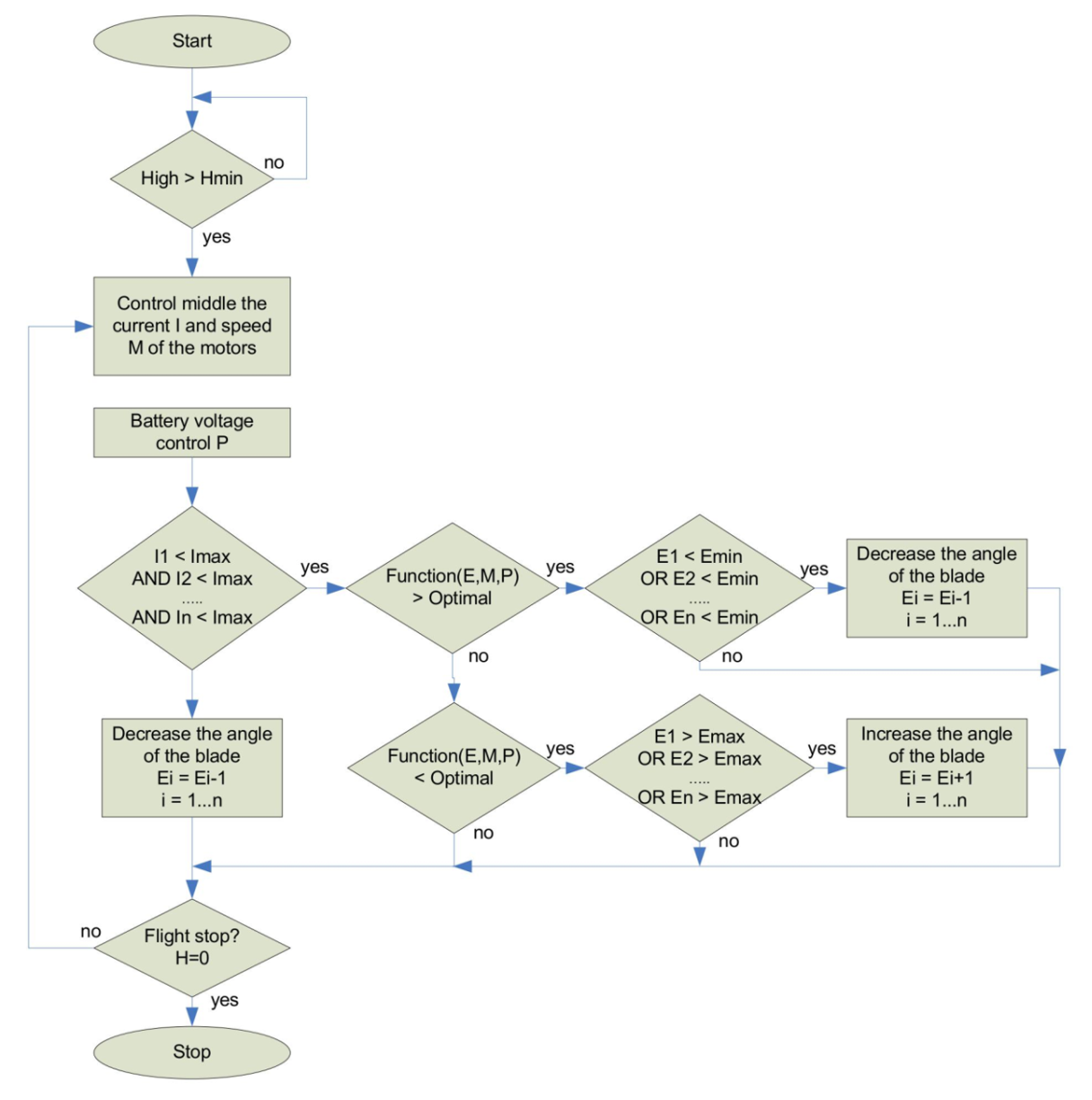
Structural Diagram of the Algorithm for Optimal Battery Energy Consumption
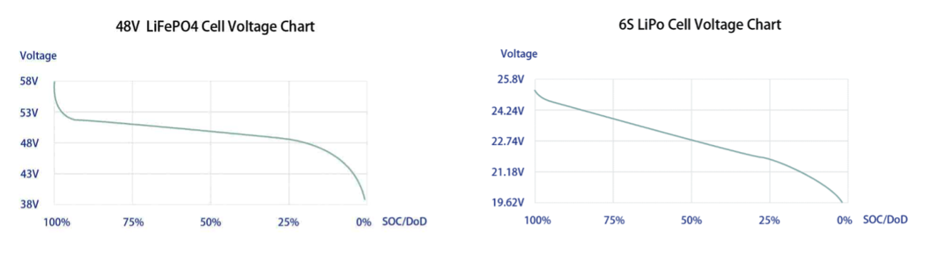
Battery Discharge Time as a Function of Discharge Current
The following code demonstrates how this algorithm operates:
1#define NUMBER_ROTOR                  4
2#define BLADE_ANGLE_START       2
3#define BLADE_ANGLE_MAX                            20
4#define HIGH_TAKEOFF                    1000                            //mm
5#define MAX_CURRENT                     10000                          //mA
6#define OPTIMAL_REG                       30000
7
8int Blade_Angle[NUMBER_ROTOR];
9
10// Optimization by speed and angle step
11int Speed_Angle(void)
12{
13             int Rotor_Current[NUMBER_ROTOR];
14             int Max_Current, Mid_Current, Mid_Speed, Index;
15             int Max_Angle, Min_Angle, Power;
16
17             while(Get_Stat_ESC() && (Get_High() > HIGH_TAKEOFF))                  // Rotors RUN and the required height has been reached
18             {
19                              Max_Current = 0;
20                              Power = Get_Power();
21                              Mid_Current = 0;
22                              Mid_Speed = 0;
23                              for(Index = 0; Index < NUMBER_ROTOR; Index++)
24                              {
25                                                Rotor_Current[Index] = Read_Current(Index);
26                                                Mid_Current += Rotor_Current[Index];
27                                                Mid_Speed += Read_Speed(Index);
28                                                if(Rotor_Current(Index) > Max_Current) Max_Current = Rotor_Current(Index);
29                                                if((Blade_Angle[Index] >= BLADE_ANGLE_MAX) Max_Angle = 1;
30                                                else if(Blade_Angle[Index] <= BLADE_ANGLE_START) Min_Angle = 1;
31                                                else {Max_Angle = 0; Min_Angle = 0;}
32                              }
33                              Mid_Current = Mid_Current/NUMBER_ROTOR;
34                              Mid_Speed = Mid_Speed/NUMBER_ROTOR;
35
36                              for(Index = 0; Index < NUMBER_ROTOR; Index++)
37                              {
38                                                if((Max_Current < MAX_CURRENT) && !Max_Angle && (Function(Blade_Angle, Mid_Speed, Power) < OPTIMAL_REG)) Blade_Angle[Index]++;
39                                                if((Max_Current < MAX_CURRENT) && !Min_Angle && (Function(Blade_Angle, Mid_Speed, Power) > OPTIMAL_REG)) Blade_Angle[Index]--;
40                                                if((Max_Current >= MAX_CURRENT) && !Min_Angle) Blade_Angle[Index]--;
41                              }
42                              Set_Blade_Angle();
43             }
44}
4. Proposed Algorithms for the Extended BLDC System: Experimental Verification and Results
The use of electronic battery section switches and stator winding reconfiguration in BLDC systems has been widely studied as a means to extend flight time and improve battery energy efficiency. Integrating artificial intelligence allows dynamic control of these switches based on real-time flight data, further enhancing system performance.
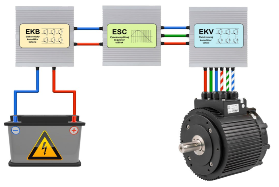
Schematic representation of the Extended BLDC System
The battery switch algorithm functions similarly to an automatic transmission: higher "gears" are engaged as speed increases. A lookup table stored in the AI control unit maps the BLDC motor RPMs at which switching between battery configurations should occur. This keeps motor RPMs within optimal efficiency ranges. For UAVs using multi-stator BLDC motors, a separate switching table is required for each stator winding configuration.
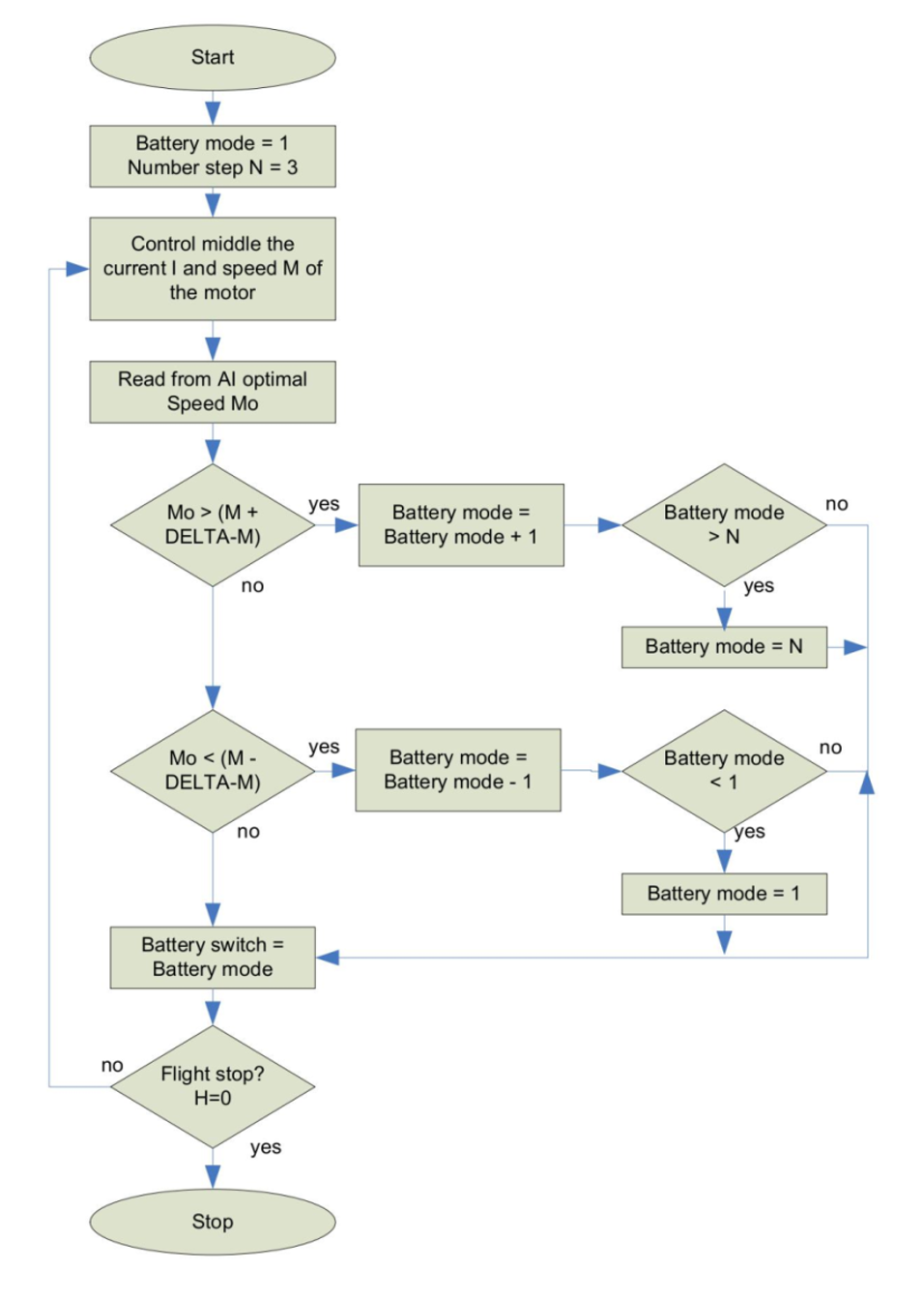
Structural Diagram of the Battery Switch Control Algorithm
This algorithm was tested on a test bench that simulated a hypothetical UAV. During testing, motor speed and propeller pitch were held constant, while the battery switch configurations were changed among 10S, 20S, and 40S voltages. During the tests, the motor's operating current and PWM pulse durations were measured.
The measurement results are summarized in Table 3.
Impact of Battery Voltage on Operating Current and PWM Pulse Duration
Motor Speed = const. 2,800 RPM | Motor Current (A) | PWM Pulse Duration (µs} |
10S | 24 | 42 |
20S | 45 | 22 |
40S | 80 | 12 |
The results indicate that at low motor speeds combined with large propeller pitch — typical of heavy multicopter operation — it is advantageous to use lower voltages. Longer PWM pulses reduce losses in the transition stages of MOSFET output stages and losses in the high-inductance stator windings. Consequently, this leads to lower heat losses.
To achieve higher rotational speeds of the propeller, it is necessary to increase the operating voltage, as low operating voltages often fail to reach the required rotational speeds. The achievable rotational speed of a BLDC motor can be calculated using the following formula:
where
RPM — propeller rotation frequency 1/min;
Q — PWM frequency, Hz;
N — Number of magnets in the rotor.
As with a robotic car gearbox, a certain level of hysteresis should be built into the algorithm to avoid undefined states at switching boundaries.
Below is the program code that explains how this algorithm works:
1#define NUMBER_ROTOR                  4
2#define NUMBER_SWITCH                                  3
3#define DELTA_SPEED                        100
4
5// Battery switch
6int Battery_switch(void)
7{
8             int Mid_Current, Mid_Speed, Opt_Speed;
9             int Battery mode = 1;
10             Set_Battery_switch(Battery mode);
11
12             while(Get_Stat_ESC() && (Get_High() > HIGH_TAKEOFF))                  // Rotors RUN and the required height has been reached
13             {
14                              Mid_Current = 0;
15                              Mid_Speed = 0;
16                              for(Index = 0; Index < NUMBER_ROTOR; Index++)
17                              {
18                                                Mid_Current = Mid_Current + Read_Current(Index);
19                                                Mid_Speed = Mid_Speed + Read_Speed(Index);
20                              }
21                              Mid_Current = Mid_Current / NUMBER_ROTOR;
22                              Mid_Speed = Mid_Speed / NUMBER_ROTOR;
23
24                              Power = Read_Power();
25
26                              Opt_Speed = Read_AI_Speed(Mid_Current, Mid_Speed, Power);
27
28                              if(Opt_Speed > (Mid_Speed + DELTA_SPEED)) Battery mode++;
29                              if(Opt_Speed < (Mid_Speed - DELTA_SPEED)) Battery mode--;
30
31                              if(Battery mode > NUMBER_SWITCH) Battery mode = NUMBER_SWITCH;
32                              if(Battery mode < 1) Battery mode = 1;
33
34                              Set_Battery_switch(Battery mode);
35             }
36}
4.2. Stator Winding Switch Algorithm
This algorithm operates similarly to an automatic transmission in a car — except instead of shifting gears, it changes the stator winding configuration to optimize either torque or rotational speed. The optimal RPM ranges and switching thresholds are preprogrammed into the PC-MCU’s internal memory and continuously monitored via tachometers (T).
A detailed description of multi-stator BLDC motor winding configurations and the electronic switching system design can be found in ,.
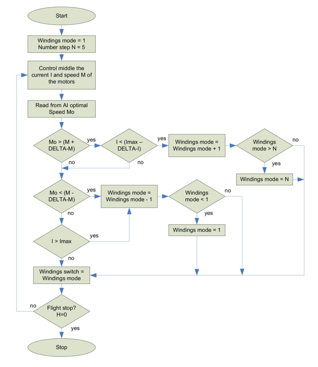
Block Diagram of the Stator Winding Switching Algorithm
The algorithm was tested on a simulation bench replicating a typical UAV environment. Throughout the experiment, voltage, motor speed, and propeller pitch were held constant. Only the winding configuration was changed — switching between “Star” and “Delta”. During the tests, current consumption and PWM pulse duration were measured.
The measurement results are summarized in Table 4.
Impact of Winding Configuration on Motor Current and PWM Pulse Duration
Motor Speed = const. 2,800 RPM | Motor Current (A) | PWM Pulse Duration (us} |
Star | 36 | 28 |
Delta | 42 | 22 |
The results indicate that for low-speed operation with high propeller pitch — typical for heavy-lift multicopters — high-inductance winding configurations are more efficient. At higher RPMs, switching to a low-inductance configuration becomes preferable, as it supports higher currents and delivers greater power output.
However, if flight conditions (cruise speed, propeller load, RPM) permit, the system should favor the configuration with the lowest current draw to maximize battery efficiency.
The following code demonstrates the logic behind this switching algorithm:
1#define NUMBER_ROTOR                  4
2#define NUMBER_SWITCH                                  5
3#define DELTA_SPEED                        100
4#define DELTA_CURRENT                                   100
5#define MAX_CURRENT                     10000
6
7// Windings switch
8int Windings_switch(void)
9{
10             int Mid_Current, Mid_Speed, Opt_Speed, Max_Current;
11             int Windings mode = 1;
12             Set_Windings_switch(Battery mode);
13
14             while(Get_Stat_ESC() && (Get_High() > HIGH_TAKEOFF))                  // Rotors RUN and the required height has been reached
15             {
16                              Mid_Current = 0;
17                              Mid_Speed = 0;
18                              for(Index = 0; Index < NUMBER_ROTOR; Index++)
19                              {
20                                                Mid_Current = Mid_Current + Read_Current(Index);
21                                                if(Read_Current(Index)) > (MAX_CURRENT + DELTA_CURRENT)) Max_Current = 1;
22                                                if(Read_Current(Index)) < (MAX_CURRENT - DELTA_CURRENT)) Max_Current = 0;
23                                                Mid_Speed = Mid_Speed + Read_Speed(Index);
24                              }
25                              Mid_Current = Mid_Current / NUMBER_ROTOR;
26                              Mid_Speed = Mid_Speed / NUMBER_ROTOR;
27
28                              Power = Read_Power();
29
30                              Opt_Speed = Read_AI_Speed(Mid_Current, Mid_Speed, Power);
31
32                              if(Opt_Speed > (Mid_Speed + DELTA_SPEED) && !Max_Current) Windings mode++;
33                              if(Opt_Speed < (Mid_Speed - DELTA_SPEED) || Max_Current) Windings mode--;
34
35                              if(Windings mode > NUMBER_SWITCH) Windings mode = NUMBER_SWITCH;
36                              if(Windings mode < 1) Windings mode = 1;
37
38                              Set_Windings_switch(Windings mode);
39             }
40}
By combining the battery switching algorithm with the stator winding switching logic, a unified control algorithm can be developed — a comprehensive strategy that considers not only battery discharge characteristics and optimal BLDC motor speeds, but also the aerodynamic behavior of propellers at various RPMs and the transient response during topology switching.
If the switching thresholds for battery sections and stator winding configurations are properly decoupled and staggered, transient phenomena — particularly peak current spikes during transitions — can be significantly reduced.
5. Conclusion
In UAV systems, the term “power-to-weight ratio” typically refers to the relationship between available energy and total flight weight. The higher the power-to-weight ratio, the longer the UAV can remain airborne. It is generally expressed as:
where
Q — battery capacity;
W — UAV takeoff weight.
However, the integration of advanced BLDC systems into the UAV introduces an additional efficiency factor into this equation:
where
K — efficiency coefficient of the BLDC system.
The more sophisticated the BLDC system — incorporating battery commutation, stator winding switching, and tightly integrated electronics — the higher its efficiency coefficient. As a result, the effective power-to-weight ratio increases, enabling longer flight durations even with the same battery capacity and takeoff weight, due to improved energy utilization. The slight weight gain from additional switching components is negligible, thanks to the compact and lightweight nature of modern electronics.
Naturally, the algorithms described in this paper are not the only ways to enhance UAV efficiency. Depending on specific UAV designs, additional software algorithms can be implemented, including:
· Point-to-Point Flight Optimization Algorithm.
This algorithm receives coordinates for the departure point (A) and destination (B), analyzes onboard battery reserves and UAV power characteristics, and dynamically adjusts flight parameters to either minimize energy consumption or maximize travel speed. If available energy is insufficient to complete the planned route, the system alerts the operator and proposes alternative solutions.
· Stator Inductance Estimation Algorithm.
High-voltage BLDC windings often exhibit significant inductance. If PWM pulses are too short, energy is not effectively transferred and is lost as heat. This algorithm estimates the inductance of the stator windings and adjusts the minimum allowable PWM pulse width to minimize energy loss — a critical function in multi-stator BLDC motors, where inductance can vary depending on the selected winding configuration.
· PWM Pulse Width Adjustment Based on MOSFET Temperature.
The heating of power-stage MOSFETs is primarily driven by switching frequency. At high propeller RPMs, rapid switching can cause excessive heating and risk component failure. This algorithm monitors MOSFET temperature and, if a defined threshold is exceeded, evaluates current flight parameters and reduces propeller speed if necessary to avoid overheating — while notifying the operator of the intervention. This method can also be combined with the inductance estimation algorithm for further optimization.
Together, these software-driven algorithms and circuit-level optimizations allow UAV performance to be significantly improved without any hardware upgrades. In many cases, deploying newer versions of a UAV may only require a remote firmware update.
This level of adaptability lays the foundation for fully autonomous UAV logistics networks — enabling smart, reliable, and scalable aerial cargo delivery.