РАСЧЕТ СИСТЕМЫ ПОДРЕССОРИВАНИЯ КАБИНЫ ЗЕРНОУБОРОЧНОГО КОМБАЙНА В ЧАСТОТНОЙ ОБЛАСТИ

РАСЧЕТ СИСТЕМЫ ПОДРЕССОРИВАНИЯ КАБИНЫ ЗЕРНОУБОРОЧНОГО КОМБАЙНА В ЧАСТОТНОЙ ОБЛАСТИ
Научная статья
Сиротин П.В.1, Лебединский И.Ю.2, *, Жилейкин М.М. 3
1 ORCID: 0000-0002-7066-5062;
2 ORCID: 0000-0002-4348-6990;
1, 2 Южно-Российский государственный политехнический университет (НПИ) имени М.И. Платова, Новочеркасск, Россия;
3 Московский государственный технический университет имени Н.Э. Баумана, Москва, Россия
* Корреспондирующий автор (ilialebedinski[at]gmail.com)
АннотацияСтатья посвящена теоретическому и экспериментальному исследованию вибрационного состояния системы подрессоривания кабины зерноуборочного комбайна с несущей системой, испытывающей в процессе эксплуатации крутильные и изгибно-упругие деформации. Актуальность исследования обусловлена возникновением резонансов собственных колебаний конструкции с источниками силовых возмущений. Представлена математическая модель колебаний кабины на упругом основании, учитывающая нелинейные упругие и диссипативные свойства конструкции несущей системы кабины. Разработанная математическая модель реализована в среде Mathcad. Программный пакет MSC Adams использовался для расчета динамических свойств несущей системы с помощью встроенного модуля расчета методом конечных элементов Flex. Учет динамических свойств несущей системы в модели позволил точно рассчитать вибрационную нагруженность кабины. Верификация модели проводилась на основе анализа сходимости значений скорректированного виброускорения на кабине комбайна, а также диапазона колебаний в линейных направлениях, полученных экспериментальным и расчетным методами.
Ключевые слова: виброизоляция, математическое моделирование, зерноуборочный комбайн, подвеска кабины, система подрессоривания, безопасность рабочего места оператора.
CALCULATION OF THE SUSPENSION SYSTEM OF A COMBINE HARVESTER CAB IN FREQUENCY DOMAIN
Research article
Sirotin P.V.1, Lebedinsky I.Yu.2, *, Zhileykin M.M.3
1 ORCID: 0000-0002-7066-5062;
2 ORCID: 0000-0002-4348-6990;
1, 2 Platov South-Russian State Polytechnic University (NPI), Novocherkassk, Russia;
3 Bauman Moscow State Technical University, Moscow, Russia
* Corresponding author (ilialebedinski[at]gmail.com)
AbstractThe article is devoted to the theoretical and experimental study of the vibration state of the suspension system of a transport-technological machine cab with the supporting system experiencing torsional and bending elastic deformations during operation. The given relevance of the study is due to the occurrence of resonances of natural vibrations of a structure with the sources of power disturbances. A mathematical model of cab vibrations on an elastic foundation is presented, which takes into account the nonlinear elastic and dissipative properties of the structure of the cab carrier system. The developed mathematical model was realized in the Mathcad. The MSC Adams software package was used to calculate the dynamic properties of the carrier system with a built-in finite element calculation module Flex. Taking into account the dynamic properties of the supporting system in the model made it possible to calculate accurately the vibration load of the cab. The model was verified based on the analysis of the convergence of the values of the full-corrected vibration acceleration on the cab of the harvesting combine, as well as the vibration range in linear directions obtained by experimental and calculation methods.
Keywords: vibration isolation, mathematical modeling, combine harvester, suspension device, suspension system, workplace safety.
Introduction A widespread problem of modern transport and technological machines (TTM) is a high level of vibration loading of the cab, its frame and panels, with the vibrations acting on the cab in the broadband range of frequencies perceived by humans. This creates uncomfortable conditions for the operator, who is constantly suffers from vibration and noise [1], [2], [3]. To analyze this problem, one of the most vibroactive machines, a high-performance combine harvester (CH), was investigated. Earlier, the experimental studies had helped to identify the features of the vibration loads formation on the CH cab. They were owing to a significant difference in the total value of vibration accelerations of the cab in the front and rear connecting points of the cabin to the carrier system. It is shown that these differences are due to elastic deformations of the carrier system of bending and torsional forms, however, at present, the vibration protection systems TTM are being designed without considering these features, that, in some cases, does not allow achieving the required level of vibration protection [4]. The aim of the study is to develop a mathematical model of the suspension system of the CH cabs, taking into account the dynamic properties of the load-carrier system. The suspension system of the cab in the most existing vehicles and transport-technological machines consists of four vibration-isolating mounts connecting the cab with its carrier system by elastic-viscous connectors, the carrier system being an absolutely rigid element of the machine structure [5], [6]. These circumstances enable to see that the kinematic effects on the cab are distributed symmetrically along its mounting points. Then, the schematic diagram of the cab suspension system will be as shown in Figure 1.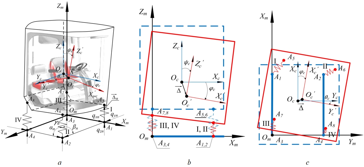
Fig. 1 – Schematic diagram of the combine harvester cab suspension system (a) and design diagrams of this system (b-side view, c-top view):
Оm Xm Ym Zm – fixed coordinate system connected by the body of the machine; Оc Xc Yc Zc – fixed coordinate system connected with the cab mass center with origin at the cab mass center Оc; Оc' Xc' Yc' Zc' – movable coordinate system connected with the cab mass center with the origin at the cab mass center Оc', after turning; n – number of vibration isolating support for cab suspension, ; j – quantity of vibration-isolating cab suspension support, ; A1, A2, A3, A4 –mount points to the supporting system, respectively, I, II, III, IV-th vibration isolation support of the cab suspension; A5, A6, A7, A8 – mount points to the cab, respectively, I, II, III, IV-th vibration isolating support for the cab suspension; ![]() – angles of inclination of the n- th vibration isolating support relative to the Xc, Yc, Zc axes of the fixed coordinate system Оc Xc Yc Zc; qxn, qyn, qzn – kinematic input action on the n- th support of the cab in a fixed coordinate system Оm Xm Ym Zm;
– angles of inclination of the n- th vibration isolating support relative to the Xc, Yc, Zc axes of the fixed coordinate system Оc Xc Yc Zc; qxn, qyn, qzn – kinematic input action on the n- th support of the cab in a fixed coordinate system Оm Xm Ym Zm; ![]() – the angles of the cab rotation, respectively, pitch, roll, course in the coordinate system Оc Xc Yc Zc;
– the angles of the cab rotation, respectively, pitch, roll, course in the coordinate system Оc Xc Yc Zc; ![]() – vector of displacement of the cab mass center relative to the position of static equilibrium in the coordinate system Оc Xc Yc Zc
– vector of displacement of the cab mass center relative to the position of static equilibrium in the coordinate system Оc Xc Yc Zc
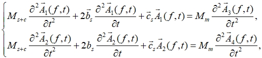
For a mathematical description, the dynamic model of the sprung cab was considered as a rigid body connected to the carrier system by means of j - vibration-isolating cab supports, which have characteristics of elasticity, damping and dry friction. Each elastic, damping force or dry friction force is schematized as three uniaxial force components. The sprung cab is ideally seen as an absolutely rigid body that has six degrees of freedom. Six generalized coordinates - three coordinates of the cab mass center and three angles of the coordinate axes rotation rigidly connected to the cab relative to the fixed coordinate axes Xc, Yc, Zc determine its position in space. The main central axes of inertia of the cabin Xc' Yc' Zc' are taken as the movable coordinate axes, in the position of its static equilibrium coinciding with the axes of the coordinate system Xc, Yc, Zc connected with the cab mass center. The displacement of the cab mass center relative to the static equilibrium position is set by the projections of the displacement vector ![]() onto the moving coordinate axes Xc' Yc' Zc', and the rotation of the moving coordinate system relative to the fixed one is given by the Euler – Krylov angles
onto the moving coordinate axes Xc' Yc' Zc', and the rotation of the moving coordinate system relative to the fixed one is given by the Euler – Krylov angles ![]() . The dynamic model of the cab vibrations is described by the differential Newton-Euler equations, which are most convenient for numerical implementation; the cab suspension system is a system with one rigid body having six degrees of freedom:
. The dynamic model of the cab vibrations is described by the differential Newton-Euler equations, which are most convenient for numerical implementation; the cab suspension system is a system with one rigid body having six degrees of freedom:
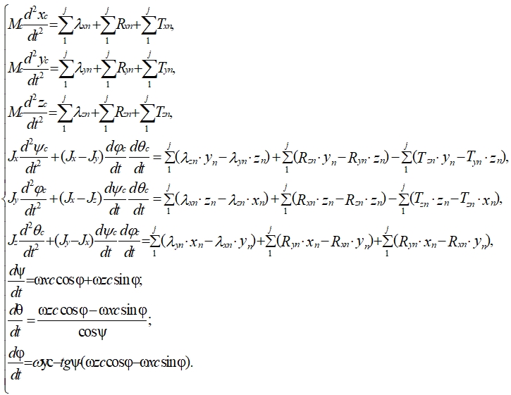 (1)
(1)
where Mc – cab mass;
xc, yc, zc – displacement of the cab mass center in the directions of the axes Xc, Yc, Zc respectively, of the coordinate system Оc Xc Yc Zc
![]() – elastic characteristic of the elastic element of the n- vibration-isolating support of the cab suspension in the axes directions, respectively Xc, Yc, Zc of the coordinate system Оc Xc Yc Zc;
– elastic characteristic of the elastic element of the n- vibration-isolating support of the cab suspension in the axes directions, respectively Xc, Yc, Zc of the coordinate system Оc Xc Yc Zc;
![]() – damping characteristic of the damping element of the n- vibration isolating support of the cab suspension in the axes directions, respectively Xc, Yc, Zc of the coordinate system Оc Xc Yc Zc;
– damping characteristic of the damping element of the n- vibration isolating support of the cab suspension in the axes directions, respectively Xc, Yc, Zc of the coordinate system Оc Xc Yc Zc;
![]() – "dry" friction characteristic of the n- vibration isolating support of the cab suspension in the axes directions, respectively Xc, Yc, Zc of the coordinate system Оc Xc Yc Zc;
– "dry" friction characteristic of the n- vibration isolating support of the cab suspension in the axes directions, respectively Xc, Yc, Zc of the coordinate system Оc Xc Yc Zc;
xn, yn, zn – coordinates of the mount point of the supporting system to the n- vibration-isolating support of the cabin suspension in the coordinate system Оc Xc Yc Zc.
![]() – the projection of the angular velocity vector of cabin oscillation on the axis of the fixed coordinate system Оc Xc Yc Zc.
– the projection of the angular velocity vector of cabin oscillation on the axis of the fixed coordinate system Оc Xc Yc Zc.
For the calculation it is necessary to determine ![]() . This is the deflection vector of the n- vibration-isolating support of the cab suspension in the coordinate system Оc Xc Yc Zc.
. This is the deflection vector of the n- vibration-isolating support of the cab suspension in the coordinate system Оc Xc Yc Zc.
The vibrations of the cab are considered small and, therefore, it is permissible to use the expression:
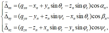 (2)
(2)
where qxn, qyn, qzn are determined experimentally by measuring the vibration under the n- vibration-isolating support of the cab suspension in the coordinate system Оc Xc Yc Zc. Experimental studies were carried out in July 2020 in the fields of the Milyutinsky district in the Rostov region of the Russian Federation. In this study, the kinematic input action was measured in the operating mode of the CH in the form of vibration accelerations under the n- vibration isolating support in the time domain. Then the measured signal was processed using double integration with the removal of trends at each iteration by eliminating the harmonic components of the signal at frequencies up to 1.5 Hz. [7].
If we represent ![]()
![]() is calculated as follows:
is calculated as follows:
![]() (3)
(3)
where ![]() are the elastic rigidity of the n- elastic element of the vibration-isolating support for the cab suspension in the coordinate system Оc Xc Yc Zc, determined experimentally using special-purpose equipment [8], [9].
are the elastic rigidity of the n- elastic element of the vibration-isolating support for the cab suspension in the coordinate system Оc Xc Yc Zc, determined experimentally using special-purpose equipment [8], [9].
If we represent ![]() .
.
![]() is calculated as follows:
is calculated as follows:
![]() (4)
(4)
where 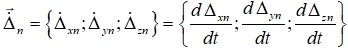 – the vector of the deflection rate of the n- vibration isolation support of the cab suspension in the coordinate system Оc Xc Yc Zc;
 ![]() – damping coefficients of the n - damping element of the vibration-isolating support of the cab suspension in the axes directions Xc, Yc, Zc respectively, in the coordinate system Оc Xc Yc Zc, determined experimentally using special-purpose equipment [8], [9].
– damping coefficients of the n - damping element of the vibration-isolating support of the cab suspension in the axes directions Xc, Yc, Zc respectively, in the coordinate system Оc Xc Yc Zc, determined experimentally using special-purpose equipment [8], [9].
If we represent ![]() in vector form
in vector form ![]() .
.
![]() is calculated as follows:
is calculated as follows:
where ![]() – damping coefficients of the n- dry friction element of the vibration-isolating support of the cab suspension in the axes directions Xc, Yc, Zc, respectively, in the coordinate system Оc Xc Yc Zc, determined experimentally using special-purpose equipment [8], [9].
– damping coefficients of the n- dry friction element of the vibration-isolating support of the cab suspension in the axes directions Xc, Yc, Zc, respectively, in the coordinate system Оc Xc Yc Zc, determined experimentally using special-purpose equipment [8], [9].
The kinematic input action on the n-vibration isolating support of the cab consists of the projections of the vector ![]() on the Xc, Yc, Zc axes in the coordinate system Оc Xc Yc Zc. In vector form
on the Xc, Yc, Zc axes in the coordinate system Оc Xc Yc Zc. In vector form ![]() .
.
The developed mathematical model was programmed and solved in the Mathcad software. The criterion for the adequacy of the model is the value of the total root mean square (RMS) vibration acceleration on the cab ![]() standardized by ISO 2631-1: 1997 [10].
standardized by ISO 2631-1: 1997 [10].
The total RMS vibration acceleration on the cab ![]() was found by the formula:
was found by the formula:
![]() (6)
(6)
where ![]() are root-mean-square values of vibration accelerations in the range of normalized frequencies in the directions of the Xc, Yc, Zc axes in the coordinate system Оc Xc Yc Zc.
are root-mean-square values of vibration accelerations in the range of normalized frequencies in the directions of the Xc, Yc, Zc axes in the coordinate system Оc Xc Yc Zc.
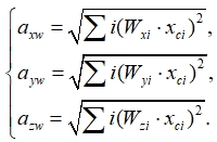 (7)
(7)
where ![]() – weight coefficient for the i- octave vibration frequency band in the directions of the Xc, Yc, Zc axes in the coordinate system Оc Xc Yc Zc.
– weight coefficient for the i- octave vibration frequency band in the directions of the Xc, Yc, Zc axes in the coordinate system Оc Xc Yc Zc.
![]() – the maximum value of vibration acceleration in the i-octave vibration frequency band in the directions of the Xc, Yc, Zc axes in the coordinate system Оc Xc Yc Zc.
– the maximum value of vibration acceleration in the i-octave vibration frequency band in the directions of the Xc, Yc, Zc axes in the coordinate system Оc Xc Yc Zc.
As a result of modeling the vibrations of the combine harvester cab with a basic suspension system without taking into account the elastic deformations of the carrier system, the value ![]() , while the experimentally obtained value
, while the experimentally obtained value ![]() . Thus, the accuracy of the model was 93%. The model error of 7% allows the calculation, but to refine the model it is necessary to obtain an error of no more than 3%. In order to identify the source of error, the spectra of operating vibrations on the cab obtained experimentally and by using simulation were compared (Fig. 2).
. Thus, the accuracy of the model was 93%. The model error of 7% allows the calculation, but to refine the model it is necessary to obtain an error of no more than 3%. In order to identify the source of error, the spectra of operating vibrations on the cab obtained experimentally and by using simulation were compared (Fig. 2).
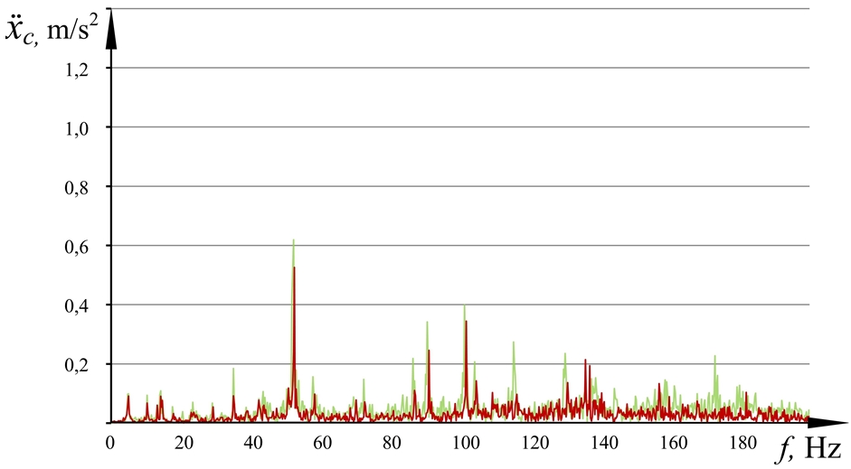
Fig. 2.1 – Spectra of the acting vibration on the combine harvester cab along the X-axis, obtained as a result of modeling without taking into account the elasticity of the carrier system (red) and experimental research (green)
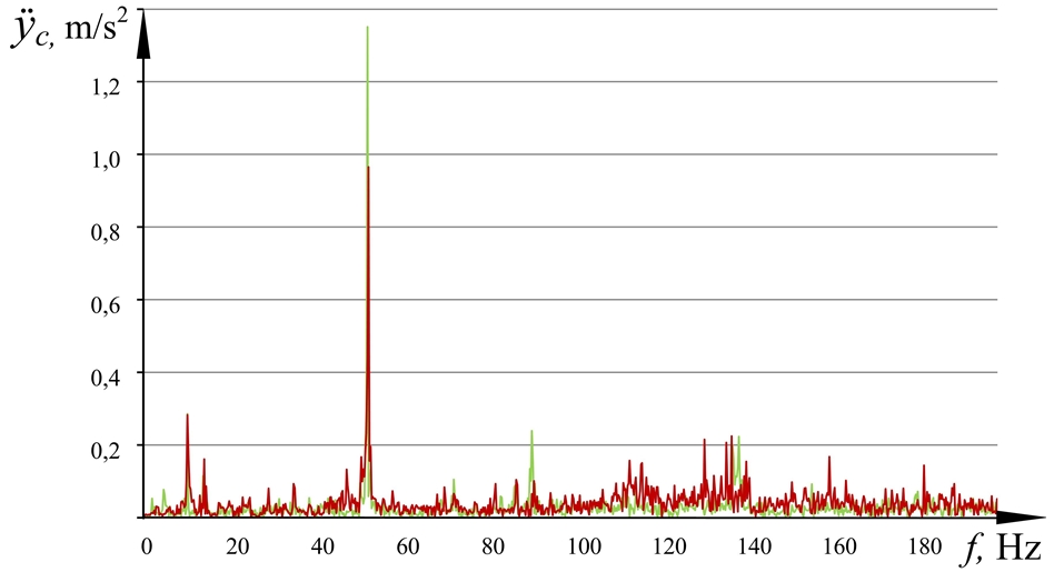
Fig. 2.2 – Spectra of the acting vibration on the combine harvester cab along the Y-axis, obtained as a result of modeling without taking into account the elasticity of the carrier system (red) and experimental research (green)
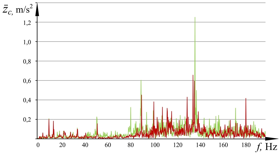
Fig. 2.3 – Spectra of the acting vibration on the combine harvester cab along the Z-axis, obtained as a result of modeling without taking into account the elasticity of the carrier system (red) and experimental research (green)
The analysis of the graphs in Fig. 2 shows that the vibration spectrum obtained by calculation at the cab mass center along the Xc axis of the coordinate system Оc Xc Yc Zc conforms the experiment. However, the vibration spectrum in the Yc and Zc directions is insufficiently adequate to the experiment in particular narrow-band ranges, with 50-56 Hz being for Yc axis and 130-140 Hz - for Zc axis. Earlier in [4], the reason for this phenomenon was considered and established, namely the elastic properties of the cab carrier system, which experiences torsional and bending elastic deformations at resonance frequencies due to the activity of vibration sources.
Therefore, in order to increase the convergence of the results of simulation and experiment, it is necessary to consider the oscillatory process occurring in the suspension system of the cab, taking into account the dynamics of two subsystems – cab vibration isolation, including vibration isolation supports, and the subsystem of the cab supporting structure. Then the suspension system of the cab can be seen as a set of interacting deformable and non-deformable bodies and is described by a hybrid dynamic model [11], [12], [13].
Taking into account the elasticity of the carrier system, the design diagram of the cab suspension system is shown in Fig. 3.
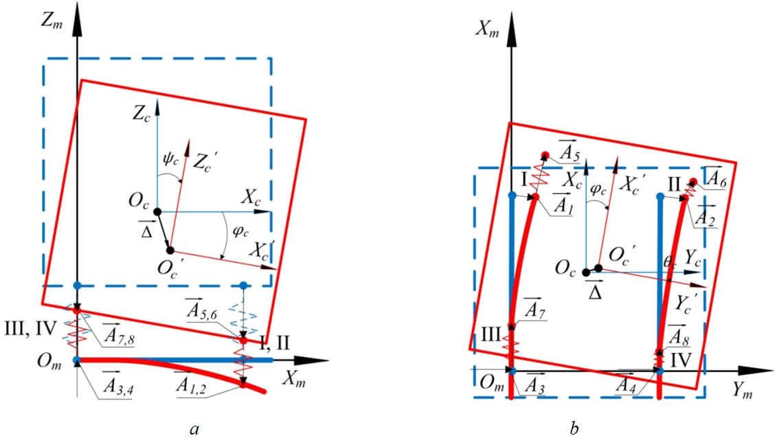
Fig. 3 – Design diagrams of the cab suspension system of a combine harvester with the elasticity of the carrier system:
a – side view; b – bottom view
In the design scheme in Fig. 3 additional designations are introduced:
![]() – displacement vector of the mount points of the I, II - (front) supports, respectively, to the cab carrier system, describing the deformation of the subframe, on the axis connected with the combine body of the coordinate system Оm Xm Ym Zm;
– displacement vector of the mount points of the I, II - (front) supports, respectively, to the cab carrier system, describing the deformation of the subframe, on the axis connected with the combine body of the coordinate system Оm Xm Ym Zm;
![]() – displacement vector of the mount points of the III, IV- (rear) supports, respectively, to the cab carrier system on the axis connected to the cab mass center of the coordinate system Оc Xc Yc Zc;
– displacement vector of the mount points of the III, IV- (rear) supports, respectively, to the cab carrier system on the axis connected to the cab mass center of the coordinate system Оc Xc Yc Zc;
![]() – displacement vector of the mount points of the I, II - (front) supports, respectively, to the cab on the axis connected to the cab mass center of the coordinate system Оc Xc Yc Zc;
– displacement vector of the mount points of the I, II - (front) supports, respectively, to the cab on the axis connected to the cab mass center of the coordinate system Оc Xc Yc Zc;
![]() – displacement vector of the mount points of the III, IV - (rear) supports, respectively, to the cab on the axis connected to the cab mass center of the coordinate system Оc Xc Yc Zc.
– displacement vector of the mount points of the III, IV - (rear) supports, respectively, to the cab on the axis connected to the cab mass center of the coordinate system Оc Xc Yc Zc.
The camber vector of the rear cab suspension supports ![]() is calculated similarly to expression (2).
is calculated similarly to expression (2).
The camber vector of the front cab suspension supports ![]() can be obtained from the relation:
can be obtained from the relation:
![]() (8)
(8)
The complexity of the calculation lies in the fact that ![]() is a frequency-related value connected with a decrease in the quality factor of the elastic vibrational system at the natural vibration frequencies. Therefore, it is advisable to calculate the vibration propagation along the cab carrier system in the frequency domain. For this, the measured vibration signal at points 3 and 4 on the cab carrier system in the time domain
is a frequency-related value connected with a decrease in the quality factor of the elastic vibrational system at the natural vibration frequencies. Therefore, it is advisable to calculate the vibration propagation along the cab carrier system in the frequency domain. For this, the measured vibration signal at points 3 and 4 on the cab carrier system in the time domain ![]() is transferred to the frequency domain using the fast Fourier transform; the amplitudes of displacements from the frequency
is transferred to the frequency domain using the fast Fourier transform; the amplitudes of displacements from the frequency ![]() are determined for a wide range of operating frequencies [5], [7].
are determined for a wide range of operating frequencies [5], [7].
Taking into account the elasticity of the cab carrier system in the directions of the Ym and Zm axes of the coordinate system Оm Xm Ym Zm, the carrier system can be represented by a single-mass oscillatory system with two degrees of freedom in the directions of linear deformations ![]() and
and ![]() as a component
as a component ![]() , describing the deformation of the front point of the cab subframe. Then, the differential equations of forced vibrations of the cab carrier system can be represented in vector form in the frequency domain:
, describing the deformation of the front point of the cab subframe. Then, the differential equations of forced vibrations of the cab carrier system can be represented in vector form in the frequency domain:
 (10)
(10)
where, ![]() –weight of the subframe and cab at the front point of the carrier system;
–weight of the subframe and cab at the front point of the carrier system;
![]() – stiffness matrix of the cab subframe in the directions of the axes Xm, Ym, Zm, respectively, of the coordinate system Оm Xm Ym Zm;
– stiffness matrix of the cab subframe in the directions of the axes Xm, Ym, Zm, respectively, of the coordinate system Оm Xm Ym Zm;
![]() – damping matrix of the cab subframe in the directions of the axes Xm, Ym, Zm, respectively, of the coordinate system Оm Xm Ym Zm.
– damping matrix of the cab subframe in the directions of the axes Xm, Ym, Zm, respectively, of the coordinate system Оm Xm Ym Zm.
The stiffness matrix of the cab subframe ![]() can be found from the expression [14]:
can be found from the expression [14]:
![]() – beam length;
– beam length;
![]() – moment of inertia of the corresponding beam section in the coordinate system Оm Xm Ym Zm,.
– moment of inertia of the corresponding beam section in the coordinate system Оm Xm Ym Zm,.
Equation 11 is applicable for calculating the stiffness of the structures in the form of beams or spars with constant cross-section, but this often does not match the topology of real structures that have a complex shape due to functional, mass-dimensional and technological limitations. Calculation of damping of a complex structure is also extremely laborious and gives significant errors. Therefore, it is reasonable to use the finite element method, for calculating the characteristics of stiffness and damping of the cab carrier system. On the basis of the investigated suspension system of the СH cab (Fig. 1 a), an equivalent simulation model was developed in the software complex for dynamic analysis of mechanical systems "MSC Adams" using the module for calculating the dynamics of deformable structures by the finite element method "Flex" (Fig. 1 b). In the model, the subframe design and the physical and mechanical properties of the material it is made from conform to the СH prototype. The subframe is connected to the machine mass center by rigid links with the locked position of the connected nodes. The mass-inertial characteristics of the cab and the elastic-dissipative properties of vibration-isolating cab supports are also taken into account.
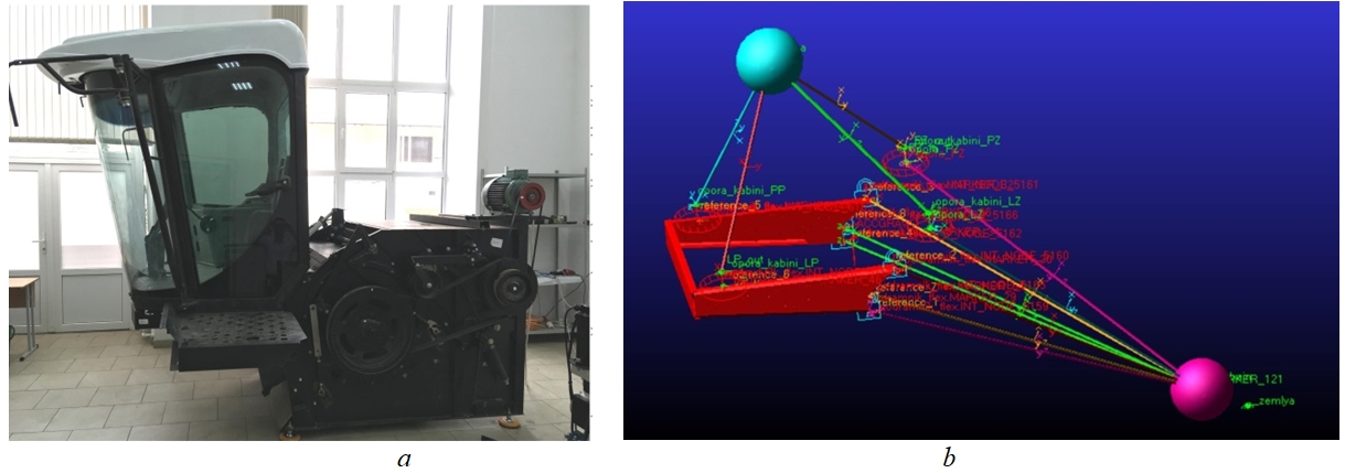
Fig. 4 – Test bench for studying the combine harvester cab suspension system (a) and the equivalent model of the cab suspension system in the MSC Adams software package (b)
Using simulation, the stiffness of the subframe is calculated ![]() , as well as the dynamic damping coefficient
, as well as the dynamic damping coefficient ![]() , which is a frequency-relation function of the frequency of forced oscillations of the carrier system.
, which is a frequency-relation function of the frequency of forced oscillations of the carrier system.
The calculated values of ![]() and
and ![]() are used to solve the system of equations 10, as a result the corrected values of the deformations of the subframe at the front points
are used to solve the system of equations 10, as a result the corrected values of the deformations of the subframe at the front points ![]() in the frequency domain are obtained, which are used in expression 8 to calculate
in the frequency domain are obtained, which are used in expression 8 to calculate ![]() . Thus, the deformation of the cab subframe at the front points in the cab coordinate system Оm Xm Ym Zm is added to the deformation of the front cab supports.
. Thus, the deformation of the cab subframe at the front points in the cab coordinate system Оm Xm Ym Zm is added to the deformation of the front cab supports.
By solving expressions 8 – 10, an input vibration signal to the suspension system of the cab in the frequency domain, which differs in the front and rear points due to the elastic deformations of the cab supporting system, was obtained.
As a result of vibration simulation of the grain harvester cab taking into account the elasticity of the carrier system -![]() ; the experimentally obtained value
; the experimentally obtained value ![]() . Thus, with regard for the elasticity of the carrier system it became possible to increase the accuracy of the model by 5.7%, from 93 to 98.7%. Also, to verify the model in the full spectrum of operating frequencies, the vibration spectra on the cab were compared (Fig. 5).
. Thus, with regard for the elasticity of the carrier system it became possible to increase the accuracy of the model by 5.7%, from 93 to 98.7%. Also, to verify the model in the full spectrum of operating frequencies, the vibration spectra on the cab were compared (Fig. 5).
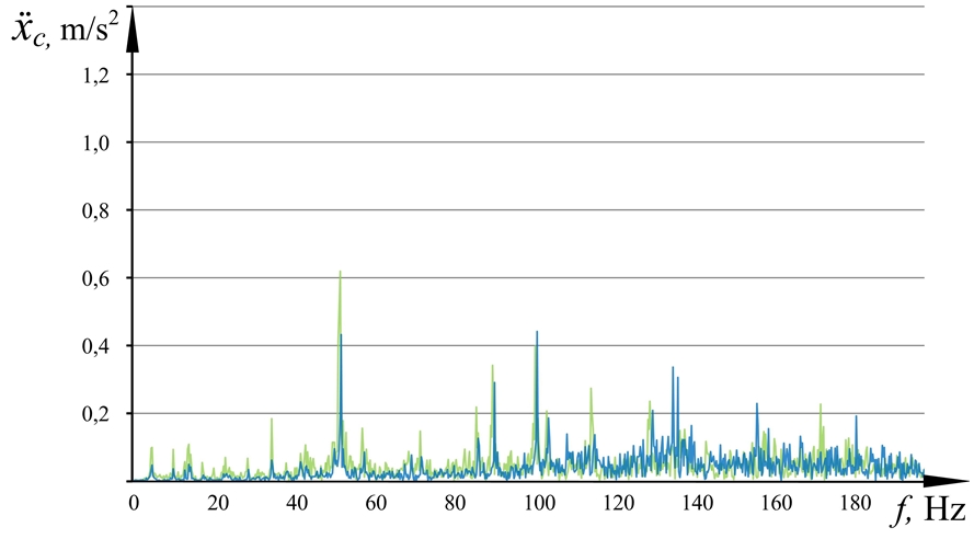
Fig. 5.1 – Spectra of acting vibration on the combine harvester cabin along the X-axis, obtained as a result of simulation taking into account the elasticity of the carrier system (blue) and experimental research (green)
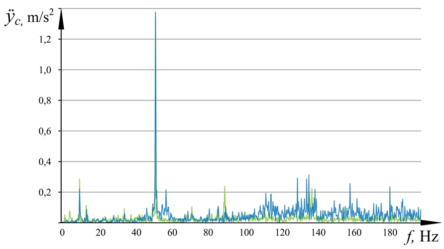
Fig. 5.2 – Spectra of acting vibration on the combine harvester cabin along the Y-axis, obtained as a result of simulation taking into account the elasticity of the carrier system (blue) and experimental research (green)
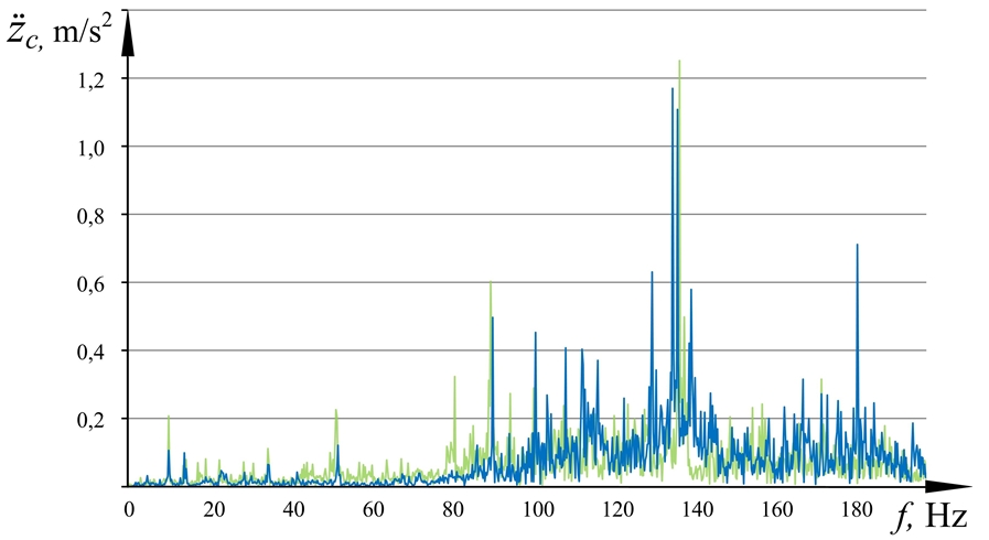
Fig. 5.3 – Spectra of acting vibration on the combine harvester cabin along the Z-axis, obtained as a result of simulation taking into account the elasticity of the carrier system (blue) and experimental research (green)
The studies carried out prove the influence of the dynamic properties of the supporting system on the formation of vibration loading of the workplace. Taking into account the results obtained, the creation of effective TTM suspension systems can have three main approaches in terms of the dynamics of carrier systems:
- creation of a sufficiently rigid support system, which will result in increasing its mass, will change the weight distribution of the vehicle and adversely affect the strength properties of the vehicle structure, as well as increase the material consumption and cost of the carrier system;
- creation of carrier systems with specified dynamic properties, the parameters of which can be determined by the above method. This direction is more relevant for the vehicles under design;
- attachment to the carrier system of additional vibrational subsystems, with inertial and dissipative influences. This solution is more relevant for the vehicles in service.
As a result, the theoretical and experimental studies of the dynamic loading of the carrier system and combine harvester cab made it possible to develop a mathematical model of the suspension system, which considers the dynamic properties of the carrier system and allows obtaining the results of the cab vibration load calculation with an accuracy of 98,7% based on the total RMS corrected value of vibration acceleration on the cab. The developed model enabled to study the efficiency of the facilities for vibration dynamic damping of the cab carrier system that in this case amounted to 5,4%. The results of the simulation were verified with experimental data obtained through field tests of the CH and bench experimental studies. The obtained tools in the form of mathematical models and theoretical relations can be useful in practice when designing the vehicles of new generations with improved operational characteristics, as well as in modernization of existing vehicles in terms of meeting sanitary requirements for vibration conditions.
Conclusion
1) It was ascertained that, in the transport-technological machines, carrier systems undergo bending and torsional elastic deformations during operation, which are due to the coincidence of the natural vibration frequencies of the carrier system structure with the vibration frequencies generated by active technological equipment, which must be taken into account when researching and designing suspension systems.
2) A mathematical model of vibrations of a mobile technological machine’s cab was developed, factoring in the nonlinear elastic-dissipative properties of the structure of the cab supporting system. This made it possible to increase the accuracy of the results of the vibration load simulation of the cab by the full root-mean-square corrected value of vibration accelerations on the cab by 5.7% in contrast to the model, which does not consider dynamics of the carrier system.
| Финансирование Исследование выполнено при финансовой поддержке РФФИ в рамках научного проекта № 19-38-90315. | Funding The work has been carried out within the framework of studies supported by the Russian Foundation for Basic Research "RFBR" within the framework of the Project No. 19-38-90315. |
| Конфликт интересов Не указан. | Conflict of Interest None declared. |
Список литературы / References
- Сиротин П.В. Анализ виброакустической нагруженности рабочего места операторов зерноуборочных комбайнов / П.В. Сиротин, И.Ю. Лебединский, В.В. Кравченко // Современные наукоемкие технологии. Региональное приложение. – 2018. – №1 (53). – С. 113–121.
- Abdul-Aziz A. Vibration transmission by combine harvester to the driver at different operative conditions during paddy harvest / A. Abdul-Aziz, A. Almosawi, Ayad J. ALkhafaji et al. // International Journal of Science and Nature. – 2016. – Vol. 7. – P. 127-133.
- Jahanbakhshi A. Vibrations analysis of combine harvester seat in time and frequency domain / A. Jahanbakhshi, B. Ghamari, K. Heidarbeigi // Journal of Mechanical Engineering and Sciences. – 2020. – Vol. 14(1). P. 6251–6258. DOI:10.15282/jmes.14.1.2020.04.0489
- Sirotin P.V. Combine harvester threshers operator workplace vibration load study and substantiation their secondary cushioning systems design principles / P.V. Sirotin, I.Yu. Lebedinsky, M. I. Sysoev // AIP Conference Proceedings. – 2019. – Vol. 2188, 050030. DOI:10.1063/1.5138457
- Черненко А. Б. Пневматические системы вторичного подрессоривания кабин многоосных автомобилей : монография / А. Б. Черненко, Б. Г. Гасанов. – Юж.-Рос. Гос. Техн. ун-т (НПИ). – Новочеркасск : ЮРГТУ (НПИ), 2012. – 156 с.
- Лебединский И.Ю. Принципы создания систем подрессоривания кабин транспортно-технологических самоходных машин / И.Ю. Лебединский, П.В. Сиротин, А.Б. Черненко и др. // Современные наукоемкие технологии. – 2019. – № 2. – С. 105–109.
- Bendat J. Random Data: Analysis and Measurement Procedures / J. Bendat, A. Pearsol. – New York: Wiley, 1971. – 240 p.
- Пат. 188124 Российская Федерация, МПК G 01 N 3/08. Стенд для статических испытаний виброизоляторов / Сиротин П. В., Лебединский И. Ю.; заявитель и патентообладатель ФГБОУ ВО "Южно-Российский государственный политехнический университет (НПИ) имени М.И. Платова» – № 2018143941; заявл. 11.12.2018; опубл. 29.03.2019; Бюл. № 10 (II ч.). – 4 с.
- Sirotin P.V. Test Bench for Vibration Isolation Systems / P.V. Sirotin, I.Y. Lebedinskii, M.M. Zhileikin et al. / Russ. Engin. Res. – 2020. – Vol. 40. – P. 551–555. DOI:10.3103/S1068798X20070229
- ISO 2631–1997. Mechanical vibration and shock-evaluation of human exposure to whole-body vibration-Part 1: General requirements. – Publication date: 1997-05-01. – International Organization for Standardization, 1997. – 31 p.
- Сиротин П.В. Обоснование и анализ применения гибридных динамических моделей для исследования систем подрессоривания кабин зерно- и кормоуборочных комбайнов / П.В. Сиротин, И.Ю. Лебединский // Вестник аграрной науки Дона. – 2018. – № 42. – С. 39-48.
- Rideout G. Simulating coupled longitudinal, pitch and Bounce Dynamics of Trucks with Flexible Frames / G. Rideout // Modern Mechanical Engineering. – 2012. – Vol. 2. – P. 176-189. DOI:10.4236/mme.2012.24023
- Warwas K. Modelling Articulated Vehicles with a Flexible Semi-Trailer / K. Warwas, I. Adamiec-Wojcik // The Archive of Mechanical Engineering. – 2013. – Vol. 80. – P. 389-407.
- Писаренко Г.С. Справочник по сопротивлению материалов / Г.С. Писаренко, А.П. Яковлев, В.В. Матвеев; под общ. ред. Г.С. Писаренко – 2-е изд. – Киев : Наук. думка, 1988. – 736 с.
Список литературы на английском языке / References in English
- Sirotin P.V. Analiz vibroakusticheskoj nagruzhennosti rabochego mesta operatorov zernouborochnyh kombajnov [Analysis of vibroacoustic loading of the operator’s workplace of grain harvesters] / P.V. Sirotin, I. Yu. Lebedinsky, V.V. Kravchenko / Sovremennye naukoemkie tehnologii. Regional'noe prilozhenie. [Modern high technology. Regional application]. – 2018. – №1 (53). – P. 113-121. [in Russian]
- Abdul-Aziz A. Vibration transmission by combine harvester to the driver at different operative conditions during paddy harvest / A. Abdul-Aziz, A. Almosawi, Ayad J. ALkhafaji et al. // International Journal of Science and Nature. – 2016. – Vol. 7. – P. 127-133.
- Jahanbakhshi A. Vibrations analysis of combine harvester seat in time and frequency domain / A. Jahanbakhshi, B. Ghamari, K. Heidarbeigi // Journal of Mechanical Engineering and Sciences. – 2020. – Vol. 14(1). P. 6251–6258. DOI:10.15282/jmes.14.1.2020.04.0489
- Sirotin P.V. Combine harvester threshers operator workplace vibration load study and substantiation their secondary cushioning systems design principles / P.V. Sirotin, I.Yu. Lebedinsky, M. I. Sysoev // AIP Conference Proceedings. – 2019. – Vol. 2188, 050030. DOI:10.1063/1.5138457
- Chernenko A.B. Pnevmaticheskie sistemy vtorichnogo podressorivanija kabin mnogoosnyh avtomobilej : monografija [Pneumatic systems of secondary suspension of multi-axle vehicles’ cabs : monograph] / A.B. Chernenko, B.G. Gasanov. – Juzh.-Ros. Gos. Tehn. un-t (NPI). – Novocherkassk: JuRGTU (NPI), 2012. – 156 p. [in Russian]
- Lebedinsky I.Yu. Principy sozdanija sistem podressorivanija kabin transportno-tehnologicheskih samohodnyh mashin [Principles of design of cab suspension systems for transport and technological self-propelled machines] / P.V. Sirotin, A.B. Chernenko et al. // Sovremennye naukoemkie tehnologii [Modern science-intensive technologies] – 2019. – № 2. – P. 105–109. [in Russian]
- Bendat J. Random Data: Analysis and Measurement Procedures / J. Bendat, A. Pearsol. – New York: Wiley, 1971. – 240 p.
- Pat. 188124 Russian Federation, MPK G 01 N 3/08. Stend dlja staticheskih ispytanij vibroizoljatorov [Bench for static tests of vibration isolators] / Sirotin P.V., Lebedinsky I.Yu.; the applicant and patentee Federal State-Budget Educational Institution of Higher Education "Platov South-Russian State Polytechnic University (NPI)". – № 2018143941; appl. 11/12/2018; publ. 29.03.2019; Bul. Number 10 (II h.). – 4 p.
- Sirotin P.V. Test Bench for Vibration Isolation Systems / P.V. Sirotin, I.Y. Lebedinskii, M.M. Zhileikin et al. / Russ. Engin. Res. – 2020. – Vol. 40. – P. 551–555. DOI:10.3103/S1068798X20070229
- ISO 2631–1997. Mechanical vibration and shock-evaluation of human exposure to whole-body vibration-Part 1: General requirements. – Publication date: 1997-05-01. – International Organization for Standardization, 1997. – 31 p.
- Sirotin P.V. Obosnovanie i analiz primenenija gibridnyh dinamicheskih modelej dlja issledovanija sistem podressorivanija kabin zerno- i kormouborochnyh kombajnov [Justification and analysis of the use of hybrid dynamic models for the study of cab suspension systems of grain- and forage harvesters] / P.V. Sirotin, I.Yu. Lebedinsky // Vestnik agrarnoj nauki Dona. [Bulletin of Agrarian Science of the Don Region]. – 2018. – № 42, Vol. 2. – P. 39–48. [in Russian]
- Rideout G. Simulating coupled longitudinal, pitch and Bounce Dynamics of Trucks with Flexible Frames / G. Rideout // Modern Mechanical Engineering. – 2012. – Vol. 2. – P. 176-189. DOI:10.4236/mme.2012.24023
- Warwas K. Modelling Articulated Vehicles with a Flexible Semi-Trailer / K. Warwas, I. Adamiec-Wojcik // The Archive of Mechanical Engineering. – 2013. – Vol. 80. – P. 389-407.
- Pisarenko G.S. Spravochnik po soprotivleniju materialov [Handbook on resistance of materials] / G.S. Pisarenko, A.P. Yakovlev, V.V. Matveev ; edited by G.S. Pisarenko. - 2nd edition. – Kiev : Nauk. Dumka, 1988. – 736 p. [in Russian]