MODELING OF THE INTEGRATING SPHERE WITH A BAFFLE

Белов Н.П.1 , Грисимов В.Н.2 , Смирнов Ю.Ю.3 , Шерстобитова А.С.4 , Яськов А.Д.6 , Яськов С.А.6
1,2,3,4,5,6Санкт-Петербургский национальный исследовательский университет информационных технологий, механики и оптики
МОДЕЛИРОВАНИЕ ИНТЕГРИРУЮЩЕЙ СФЕРЫ С ЭКРАНОМ
Аннотация
Выполнено численное моделирование интегрирующей сферы с экраном, который может располагаться вблизи центра сферы. Приведены результаты анализа распределения освещенности внутри сферы такой конфигурации. Проведено измерение коэффициентов диффузного отражения медико-биологических объектов.
Ключевые слова: интегрирующая сфера, освещенность, коэффициенты диффузного отражения, экран.
Belov N.P.1, Grisimov V.N.2, Smirnov Yu.Yu.3, Sherstobitova A.S.4, Yaskov A.D.5, Yaskov S.A.6
1St. Petersburg National Research University of Information Technologies, Mechanics and Optics; 2M.D., St. Petersburg State I. P. Pavlov Medical University, ; 3Postgraduate student, Saint-Petersburg National Research University of Information Technologies, Mechanics and Optics; 4Ph.D in Technical sciences, Saint-Petersburg National Research University of Information Technologies, Mechanics and Optics; 5D.Sc. in Technical sciences, professor, Saint-Petersburg National Research University of Information Technologies, Mechanics and Optics; 6Saint-Petersburg National Research University of Information Technologies, Mechanics and Optics
MODELING OF THE INTEGRATING SPHERE WITH A BAFFLE
Abstract
Numerical modeling of the integrating sphere with a baffle which can be situated near the center of the sphere is accomplished. Results of the analysis of the irradiance distribution within the sphere of such configuration are given. Measuring of biomedical objects’ diffuse reflection indexes is conducted.
Keywords: integrating sphere, irradiance, diffuse reflection indexes, baffle.
Integrating sphere is widely applied for measuring of diffuse reflection indexes of different objects. Biomedical objects including ones used in aesthetic stomatology also represent substantial interest. A configuration, in which light from a light source strikes upon sphere’s walls and a detector registers light flux reflected from a sample, requires to prevent a direct light falling from the light source upon the sample. This can be achieved by using a baffle installed within the sphere. The purpose of this work was a numerical analysis of the irradiance distribution for the integrating sphere with the baffle and a research of biomedical objects’ diffuse reflection indexes. The configuration of such sphere is represented in fig. 1.
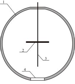
Fig. 1 - Configuration of integrating sphere with a baffle. 1 – a sphere, 2 – a baffle, 3 – an optical fiber, 4 – a port for sample’s installation
A geometry of the integrating sphere represented in this figure may be interesting, whereas, firstly, more uniform distribution of irradiance on the sphere’s surface due to axial symmetry of such construction can be achieved; secondly, installation of the light source within the sphere raises its light efficiency; thirdly, the usage of the optical fiber as a collector of reflected light simplifies detection and transmission of the reflected light to the photodetector (including input of light into monochromator). It is important to note that the baffle was applied as a holder of the optical fiber. Besides, if the configuration of the integrating sphere with the external light source and photodetector was formerly analyzed, e. g. in [1, 2], such data for the sphere with the baffle (the configuration in fig. 1) in the known literature are absent.
Calculation
It is necessary to know the irradiance distribution within the sphere for a determination of construction functionality. We accept that reflection of light take place according to the Lambertian. So irradiance within the sphere can be found by the matrix method [1, 2]. This method assumes the partition of the sphere’s internal surface into circular zones with equal reflection indexes and irradiances (fig. 2).
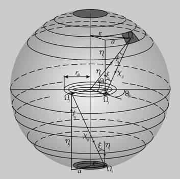
Fig. 2 - Image of the sphere partitioned on N circular zones, and elements for several zones (for calculation by the matrix method)
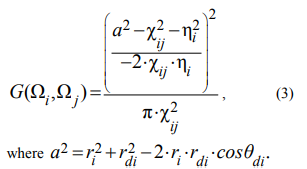
The radiation exchange between elements of two zones at points with coordinates Ωi and Ωj is determined by configuration factors G(Ωi,Ωj) as:
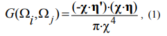
where χ – a vector directed from Ωjto Ωi, η, η’ – normal unit vectors, χ – a distance between points Ωiand Ωj.
For the further analysis it is necessary to divide surfaces taking part in the radiation exchange into the sample’s surface, the upper and lower surfaces of the sphere and the baffle. Configuration factors G(Ωi,Ωj) are determined according to the geometry of interactive regions: an upper hemisphere – an upper hemisphere; a lower hemisphere – a lower hemisphere; an upper hemisphere – a lower hemisphere; a lower hemisphere – an upper hemisphere; an upper hemisphere – an upper surface of the baffle; a lower hemisphere – a lower surface of the baffle; an upper hemisphere – a sample’s surface; a lower hemisphere – a sample’s surface; a lower surface of the baffle – a sample’s surface.
Quoted configuration factors G(Ωi,Ωj) for the radiation exchange between zones of the internal surface of the sphere, zones of sphere’s surface and the sample’s surface are the same as ones for the sphere without the baffle; they are represented in [1].
In the quoted configuration of the sphere with the baffle (fig. 1) it is also necessary to take into account an interaction between zones of the sphere’s surface and the baffle’s surface, as well as of the sample’s surface and a lower surface of the baffle. Geometric relations required for calculation of these G(Ωi,Ωj) factors at the orientation of the baffle in the center of the sphere are represented in fig. 2.
Configuration factors determining the radiation exchange between the upper hemisphere and upper surface of the baffle, the lower hemisphere and lower surface of the baffle, are identical:
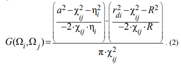
Configuration factor for interaction between the lower surface of the baffle and the sample is:
ri – a radius of the zone, R – a radius of the sphere.
The irradiance of the zone i can be represented as well as in [1] by the equation:

where Н0 – the irradiance from the light source, H(Ωj) – the irradiance of the zone j, ρ(Ωj) – its reflection index, λj – a weighting factor determined by integration over the surface of the zone, i and j – indexes of the zone.
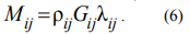
So as well as in [1] for the quoted sphere the problem is represented by matrix equation:
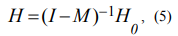
where I – the identity matrix, М – the transfer matrix:
The irradiance H0 from the light source is set as the uniform distribution within the circle on the upper surface of the baffle. The diameter of this circle is the same as the one of the entrance port. It was supposed that the fiber collector didn’t effect on the distribution within the sphere.
The directions on each of circular zones on the surface of the sphere (fig. 2) with indexes  and
and  are set by respective angles within
 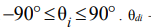 – a horizontal angle in the plane of the baffle:
  – a radius of the baffle. The central point is situated in the center of the sphere. Weighting factors λj correspond to squares of elementary sections of circular zones.
Number of zones used in calculations was N=334. The calculation of baffle’s covering of several zones at the interaction of the upper and lower hemispheres as well as the upper hemisphere and the sample was performed by partition of baffle’s circular zones on angle sectors (the respective angle was  ) and by integration of irradiance over every sector for which there was not baffle’s covering of the radiation flux. For the calculation of the entrance port’s effect (fig. 1, 2) reflection index of the respective region in the upper hemisphere was equal to zero.
Results
Calculation results are referred to the integration sphere with the baffle. This sphere was used in spectral devices similar to ones represented in [3] and had following optical-geometric characteristics: an internal diameter of the sphere was 70 mm; diameters of entrance and outlet ports – 15 mm; a diameter of the baffle – 23 mm; a diameter of the fiber collector – 1 mm; reflection indexes of the sphere and baffle 0.96. In calculations samples had reflection indexes within 0.1-0.9.
Calculation data are represented in diagram form (fig. 3). It is shown the irradiance distribution (Н-Н0) within the sphere calculated for five samples with different diffuse reflection indexes. Numbers of circlular zones is also represented in fig. 3.
The most nonuniformity of irradiance has the upper hemisphere on which radiation flux reflected from the upper plane of the baffle. In the same figure it can be seen that the common irradiance decreases with the lowering of sample’s reflection index. This forms a basic error in the substitution method.
 on surfaces of the sphere, sample and baffle. 1 – an upper hemisphere, 2 – a lower hemisphere, 3 – a sample’s surface, 4 – a lower surface of the baffle, 5 – an upper surface of the baffle")
Fig. 3 - Irradiance distribution (Н-Н0) on surfaces of the sphere, sample and baffle. 1 – an upper hemisphere, 2 – a lower hemisphere, 3 – a sample’s surface, 4 – a lower surface of the baffle, 5 – an upper surface of the baffle
A comparative analysis of calculation data for the quoted sphere and sphere without a baffle where the irradiance from the light source fell on the sample (at permanence of other optical-geometric parameters) showed that the irradiance distribution on the sample’s surface was uniform within 
It was also interesting to analyze the effect of baffle and fiber collector’s sizes on the irradiance distribution in the examined configuration of the sphere. Additional calculations accomplished for the sphere with the baffle (fig. 1) showed that variation of its diameter within 10.45-23.00 mm practically did not effect upon the irradiance distribution on the sphere’s surface as well as on the sample’s surface. In calculations simulating the effect of the optical fiber reflection index of baffle’s central region (a radius of which was 1.35 mm) was equal to zero. Calculation results showed that changes of the irradiance were less than one percent.
Experiment
For the experimental check of quoted calculation results the comparison analysis of different biomedical objects’ reflectance spectra was conducted.
The laboratory spectrometer similar to one considered in [3] was used for measuring. It included a spectrometer unit based on a polychromator with a concave grating; data collection and processing electronic system with operable software. The reflectance spectrum was registered by CCD line sensor (SONY ILX 511) output signal of which was processed by electronic system. Software allowed to output measuring data by way of a diagram, a numerical array as well as to print and save them.
Calibration testing of the laboratory spectrometer was conducted by standard diffuse reflectors (gray standards). References had reflection indexes within 0.5-0.85. Biomedical filler materials applied in stomatology represented composites “Charisma” and “Estelite” before and after polymerization. Measuring was done in visible band (380-760 nm). Experimental data for the sphere without a baffle but with external light source and photodetector (an internal diameter of the sphere was 180 mm) were compared with ones for the quoted sphere with the baffle (fig. 1) (an internal diameter was 70 mm). Both spheres had allied ratios of the sphere’s internal surface area to the summarized surface area of entrance and outlet ports. Measurement errors for five references with reflection indexes of ρ = 0.1; 0.3; 0.5; 0.7 and 0.9 are represented in table 1.
As is evident from the table, the measurement error remains practically inalterable for both geometries of sphere.
Table 1 - Relative measurement errors for references with diffuse reflection indexes of 0.1; 0.3; 0.5; 0.7 and 0.9 for integrating sphere with the baffle and without it
| Reflection index ρ of the sample, relative units | Sphere with a baffle | Sphere without a baffle |
|
0.1 |
0.0467 |
0.0458 |
|
0.3 |
0.0453 |
0.0444 |
|
0.5 |
0.0439 |
0.0430 |
|
0.7 |
0.0425 |
0.0416 |
|
0.9 |
0.0411 |
0.0402 |
So the usage of the baffle within the integrating sphere does not contribute an error in measurement data. Generally, it confirms the thesis that the main factor determining the basic photometric error of diffuse reflection index measurement is the ratio of the sphere’s internal surface area to the surface area of entrance and outlet ports [4].
Reflectance spectra of explored samples “Charisma” and “Estelite” before and after polymerization are represented in fig. 4. The precision of reflection index measurement data for both configurations of the sphere was mere  for all examined references and samples within said spectral region. So, generally, presented experimental data confirmed calculation results.
Conclusions
By virtue of quoted calculation and experimental data, it is possible to conclude that the baffle in the configuration of the sphere represented in fig. 1 does not effect on sample’s irradiance nonuniformity leading to the photometric error. The light source can be installed above the baffle within the sphere as far as according to calculation data represented in fig. 3, the irradiance nonuniformity of the upper hemisphere does not effect on the measurement error.
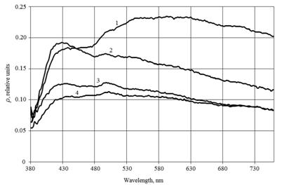
Fig. 4 - Reflectance spectra of explored samples: 1 – “Charisma” before polymerization, 2 – “Charisma” after polymerization, 3 – “Estelite” before polymerization, 4 – “Estelite” after polymerization
References
1. Tardy H. L. Matrix method for integrating-sphere calculations // J. Opt. Soc. Am. A, 1991. – Vol. 8. – P. 1411 – 1418.
2. Clare J. F. Comparison of four analytic methods for the calculation of irradiance in integrating spheres // J. Opt. Soc. Am. A, 1998. – Vol. 15. – P. 3086 – 3096.
3. Белов Н. П., Грисимов В. Н., Яськов А. Д. Лабораторный спектрометр для исследования коэффициента отражения и определения параметров цветности диффузно отражающих объектов // Известия вузов. Приборостроение, 2010. – № 7. – С. 74 – 78.
4. Prahl S. A. Inverse adding-doubling for optical property measurements [Electronic resource] URL: http://www. omlc.ogi.edu/software/iad/ (date of access: 27.10.2010).