ЭФФЕКТ УГЛА НАКЛОНЕНИЯ ПЛИТКИ НА МАКСИМАЛЬНУЮ ТЕМПЕРАТУРУ УПОРНОГО ПОДШИПНИКА
ЭФФЕКТ УГЛА НАКЛОНЕНИЯ ПЛИТКИ НА МАКСИМАЛЬНУЮ ТЕМПЕРАТУРУ УПОРНОГО ПОДШИПНИКА
Аннотация
Применение упорных подшипников в различных инженерных конструкциях порождает проблемы теплового состояния, которое приводит к износу неподвижных или наклонных вкладышей подшипника. Избежать этих проблем можно, применяя в процессе проектирования соответствующие методы и численные алгоритмы, позволяющие рассчитывать статические характеристики подшипника, в том числе максимальную температуру масляной пленки. Знание теплового состояния подшипника должно обеспечивать надежную и долговечную работу подшипника и является важным для разработчиков упорных подшипников.
В данной статье представлены результаты расчетов некоторых статических характеристик упорного подшипника с наклонным вкладышем, в том числе его максимальной температуры масляной пленки под действием угла наклона вкладыша. Для решения уравнений геометрии, Рейнольдса, энергии и вязкости применялось численное решение методом конечных разностей. Рассматривалась адиабатическая масляная пленка, ламинарное течение в зазоре подшипника. Разработанный численный алгоритм обеспечивает расчет характеристик подшипника и создает инструмент для решения тепловых задач. В расчетах предполагались различные значения рабочих скоростей.
1. Introduction
Tilting pads thrust bearings are applied in the bearing system of the water turbines, main shafts of marine steam turbines, spindles of heavy machine tools, gears, etc. These bearings can transfer large thrust loads from rotating shafts to supporting structures.
Development of modern rotating machinery is strictly bound with an increase in applied loads, higher rotational speed and generated power. From this technical point of view, the knowledge of pad temperature and particularly its maximum temperature is very important.
The maximum oil film temperature is an important limitation that do not allow for any increase in loads and rotational speeds of thrust bearings. The increase in the temperature of the lubricating oil is caused by the amount of heat released in the oil film during the operation of the bearing. Hence, the researchers' interest in thermal phenomena occurring in thrust bearings , , and , .
The sliding surface of the tilting pad can be made from the traditional white metal or special polymers. The strengths properties of such materials, their permissible operating temperatures, create limitations on the maximum oil film temperature. Therefore, taking into account thermal phenomena in the process of designing and calculating a bearing seems necessary. An additional problem that is important from the technical point of view is the transition from mixed friction to fluid friction and vice versa during start-up and stopping phase of the machine. The period of mixed friction can generate very inconvenient condition of bearing operation resulting in increase of temperature in oil film , , , and , , .
The tribosystem of thrust bearing consists of tilting or fixed pads and thrust collar, the parts that are separated by the layer of lubricant. The heat generated in the layer of lubricant determines the thermal behaviour of such tribosystem and has a decisive effect on its reliable operation. Improper choice of bearing geometrical and operational parameters generates thermal problems of wear and finally the failure of bearing and bearing system.
The boundary parameters limiting the operation of thrust bearings are: minimum thickness and maximum temperature of oil film (Fig. 1a); the horizontal line (boundary operation) results from limiting stress levels around the pad pivot . From the point of proper exploitation of rotating machine with tilting pad bearing, the control of the pad temperature is very important. It results from the calculations and measurements of pad temperature that point out on the hot spot region that is placed at the outer edge of the trailing edge. Then, the thermocouple should be located in this region (Fig. 1b and Fig. 1c).
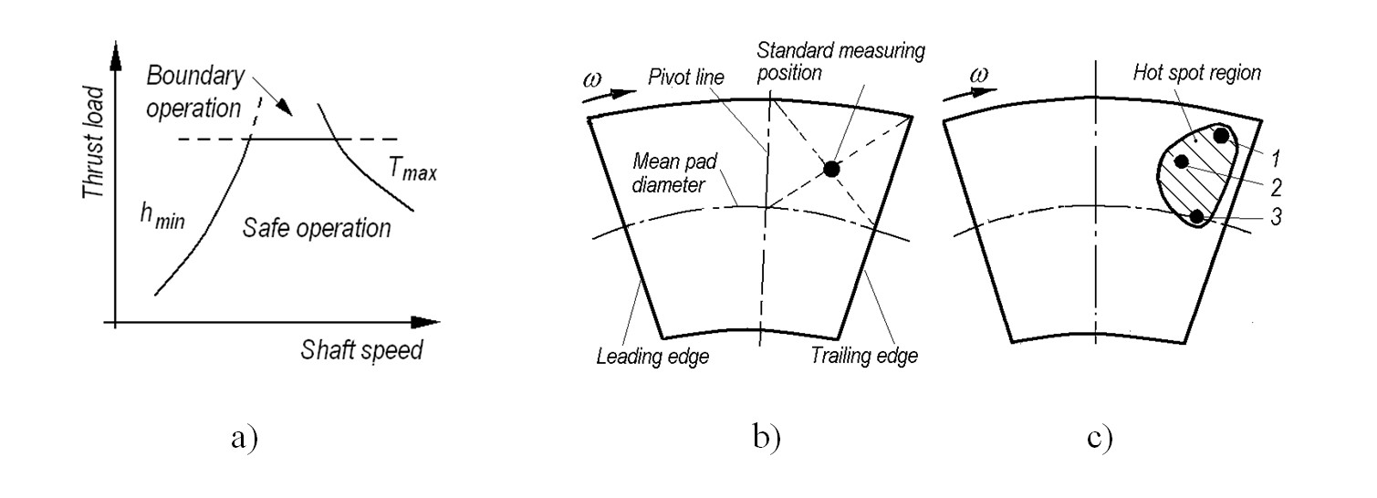
Figure 1 -
Parametrs limiting the operation of thrust bearings (a), the regions of largest oil film temperatures (b) and the standard position of temperature measurements (c):
ω – angular speed of thrust collar; 1, 2, 3 – point of highest temperature; shadowed field – range of larges temperatures in oil film
Note: based on [1]
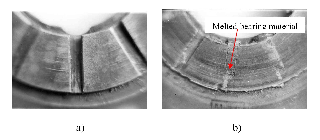
Figure 2 - View of the axial part of radial-axial (fixed pads) bearing of high-speed compressor:
a – unloaded side; b – loaded side
Note: melted bearing material in the radial oil grooves
Static characteristics of tilting-pad thrust bearing are affected by the geometry of oil film, including the tilt angles of the pad. These angles should be considered in two planes, however one of them, in the direction of pad rotation, is more important and has larger effect on the bearing characteristics.
This paper presents the results of computation of the oil film maximum temperature of thrust bearing under effect of the pad tilt angles. The numerical algorithm for calculation of thrust bearing with tilting pads and the assumptions of laminar and adiabatic model of oil film was applied.
2. Oil film thickness, pressure and temperature distributions
The lubricant gap forms an average thickness hs which is the result of tilting pad rotation with regard to axes x and y intersecting at the point s with coordinate (Rs, δ0, hs); this point correspond to the support point of pad.
Schematic view of tilting pad geometry shows Fig. 3. Oil film thickness is described by Eq. (1).
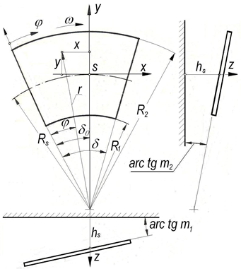
Figure 3 - Schematic view of tilting pad and oil film geometry:
R1, R2 – inner an outer radius of the thrust tilting pad, δ – angle of the thrust tilting pad length
where: – dimensionless oil film thickness, hs – oil film thickness at the point s with coordinates (Rs δ0), m1, m2 – tangents of pad tilt angle, r,
– cylindrical system coordinates, Rs – mean radius of the thrust pad, δ0 – angle of the insert support line.
The flow of mass and energy in a lubricating film govern three basic laws: conservation of mass, maintaining the quantity of motion and the energy conservation. Applying these laws, the Navier-Stokes and geometry of oil film equations allow obtaining the Reynolds, energy, viscosity equations , , , , ; their solution gives the static characteristics of thrust tilting pad bearing for adiabatic or diathermal model of oil film.
Equation (2) describes the distribution of the pressure in the oil film in dimensionless form.
where: – dimensionless oil film pressure,
,
– coordinates of cylindrical system, δ – insert angle,
– dimensionless dynamic viscosity of lubricant.
Energy equation transformed into dimensionless form (Eq. 3) gives the oil film temperature distribution.
where: – temperature,
– Peclet number
,
– specific heat of oil,
– oil density, K – heat transfer coefficient,
– average temperature of oil film,
– thermal conductivity coefficient of the oil,
– flow of oil in radial and peripheral directions.
The dimensionless viscosity of lubricant describes exponential Eq. (4) .
where: A, B – factors including the influence of temperature on the oil viscosity, T0 – reference temperature.
Iterative solution of equations (1) through (4) gives the fields of oil film pressure, temperature and viscosity. Application of the parabolic approximation , , allows determination of temperature values on the boundaries of bearing. In the regions of negative pressure of oil film and on the bearing edges, nil pressure values were considered, i.e.
.
The system of equations (1) through (4) was solved numerically by means of finite difference method. It was found that the sufficient accuracy of computation can be obtained applying the net with the number of nodes l x m = 11 x 21. In order to find the discrete values of the functions at individual mesh nodes, the equations (2) and (3) were transformed into the form of differential equations. In the pressure distribution equation (2), the derivatives were replaced by the (central) difference quotients: In case of the energy equation (3), it was more convenient to use backward difference quotients , , .
3. Results and discussion of calculations
Developed numerical algorithm allows calculation of the bearing static characteristics, i.e. oil film thickness, pressure, temperature and velocity distribution as well as the quantities characterizing such properties as: bearing load capacity, friction torque, coordinates of oil film resultant force, oil streams as well as maximum values of pressure and temperature.
The following geometrical data were assumed: oil film thickness hs at the point with coordinates (Rs δ0), inner and outer radius of the plate R1 and R2, tangents m1 and m2 of tilt angle of pad with regard of axis sy and sx, δ, δ0 – angle of pad and angle of supported line, were assumed respectively. Operational data were as follows: dynamic oil viscosity coefficient , dynamic oil viscosity coefficient at the reference temperature
0, thermal conductivity coefficient in the oil
, thermal conductivity coefficient in the pad
t, factors a, b including an effect of temperature on the oil viscosity, average temperature of oil film Tc, reference temperature T0, temperature of oil at inlet edge Tp, heat transfer coefficient kt. The range of rotational speeds varied from 50 rpm through 1000 rpm.
Different pad tilt coefficents m1 and m2 were considered. Dimensions of tilt pad: inner, external and mean radius were r1= 0,10915 and r2= 0,20915, rmean= 0,1592 respectively. T0=200C, η0=0,297 Nsm-2ρ0= 898kg/m3, cp= 1980J/kg0C, λ= 0,1450 J/ms0C. Assumed nodes number were: peripheral direction m=21 and radial direction n=6.
Exemplary results of computations that were obtained at assumed bearing parameters are given in Fig. 4 through Fig. 15; in these figures, the oil film thickness at the point with the coordinates (Rs δ0) hs was assumed as 0,213E-03. Dimensionless oil film thickness at assumed values of tilt angles m1 =-0,0013685 and m2=0,00076 shows Fig. 4; the lowest values are at the trailing edge of pad (j=21).
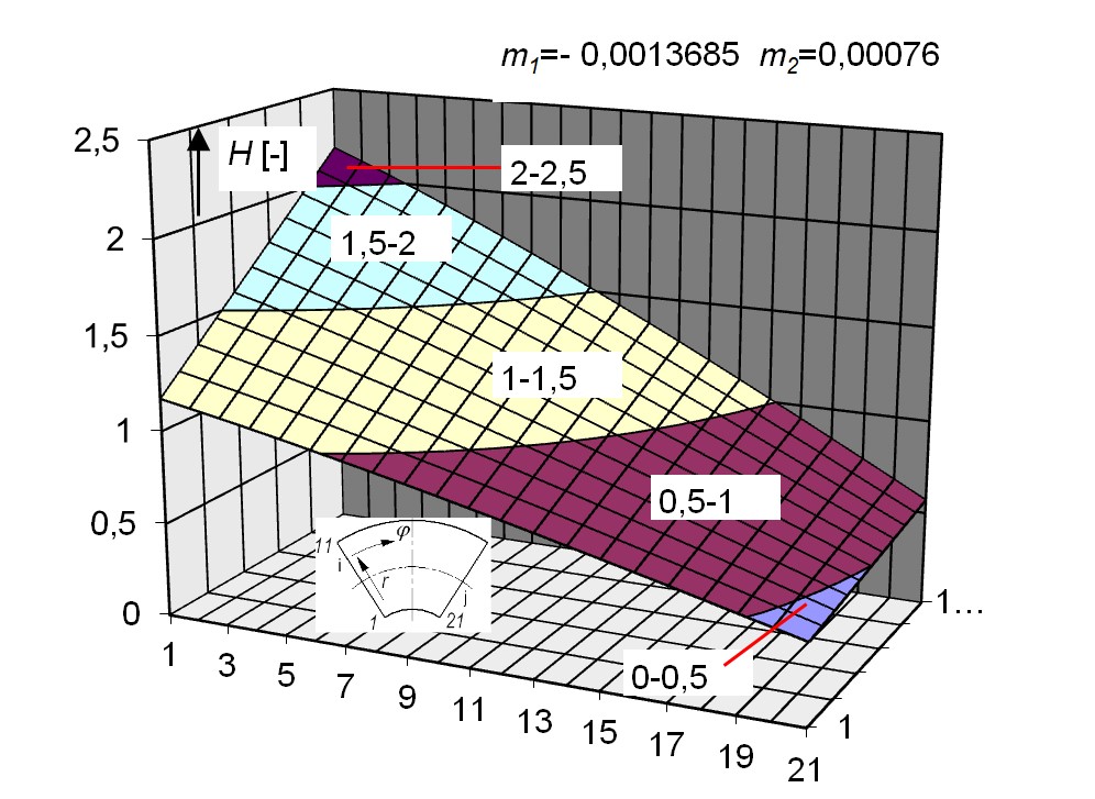
Figure 4 - Dimensionless oil film thickness at assumed values of tilt angles of tilting pad
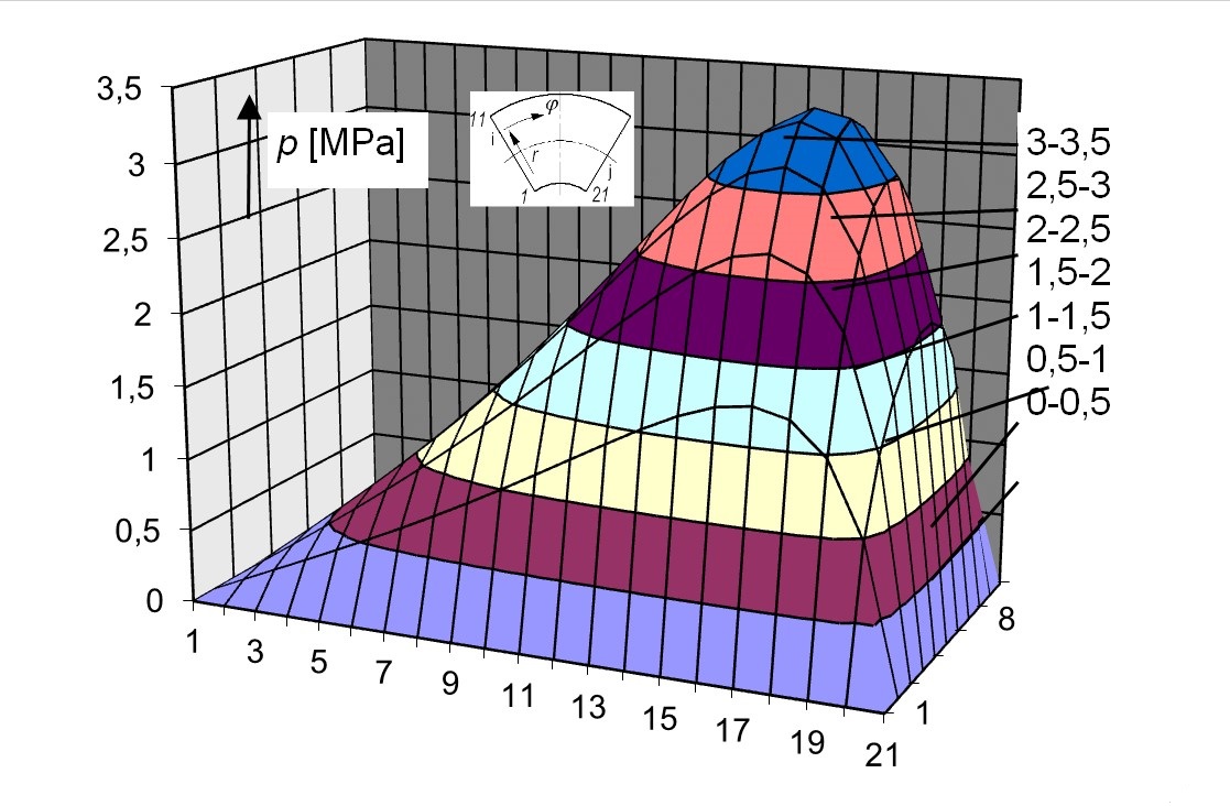
Figure 5 - 3D oil film pressure distribution on the thrust-tilting pad
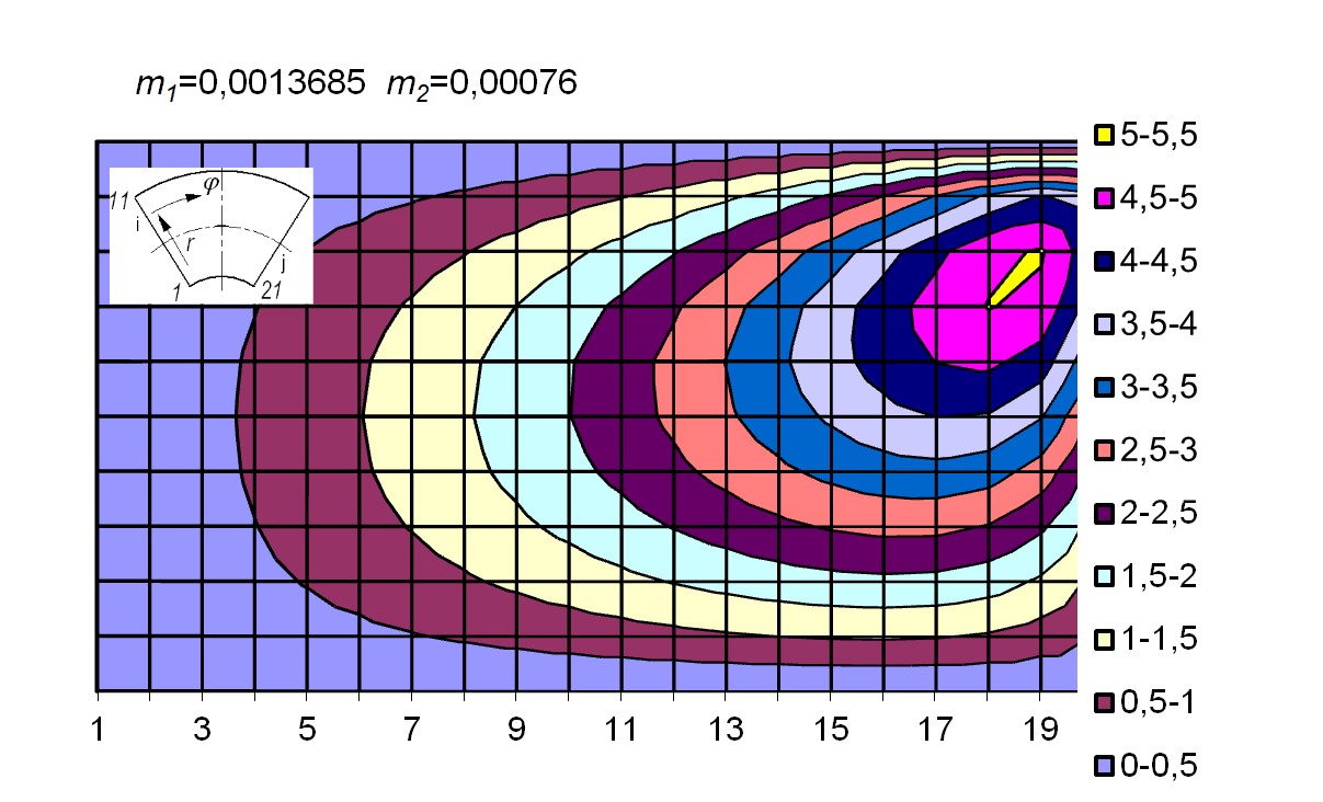
Figure 6 - Isobars of oil film pressure on the tilting pad
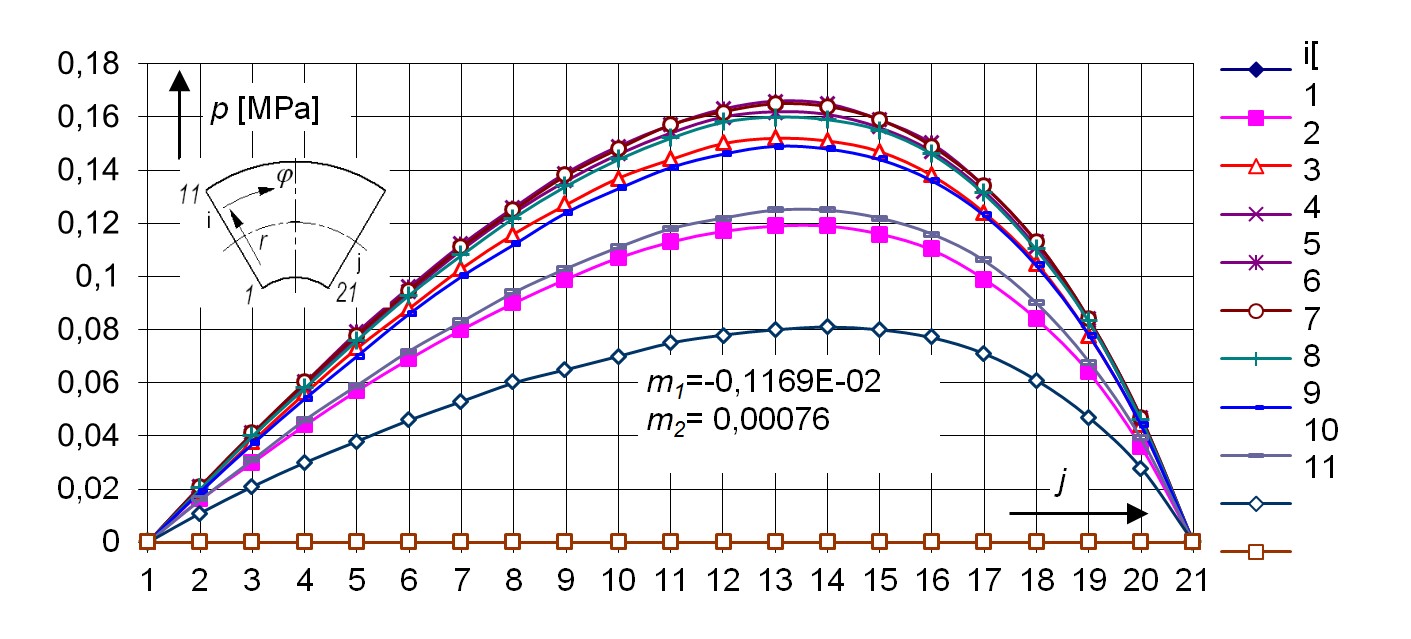
Figure 7 - Oil film pressure distribution in the peripheral direction on the tilting pad
An effect of tilt angle m2 on maximum value of oil film pressure pmax and temperature Tmax at different rotational speeds of thrust collar and for constant value of m1 show Fig.10a (m1 ≠ 0, m2 = 0) and Fig. 10b (m1 ≠ 0 and m2 = 0). In both cases, an increase in the rotational speeds causes the increase in pmax and Tmax. However, nil value of tilt angle m2 generates higher Tmax (e.g. at n=300 rpm and for m1=-0,01469 and m2=0 then Tmax ≈550C, but Tmax≈450C at m1=-0,01469 and m2=-0,0007).
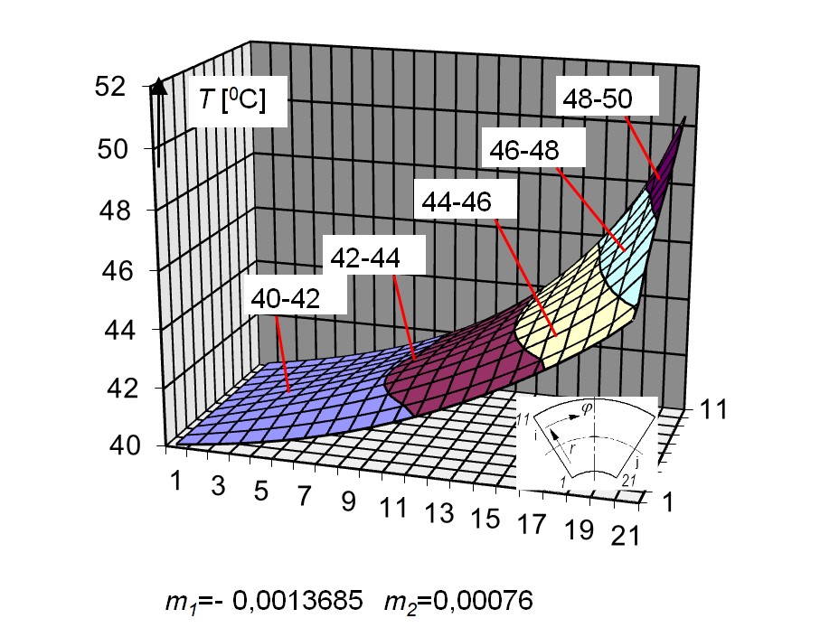
Figure 8 - Oil film temperature distribution (3D) on the tilting pad
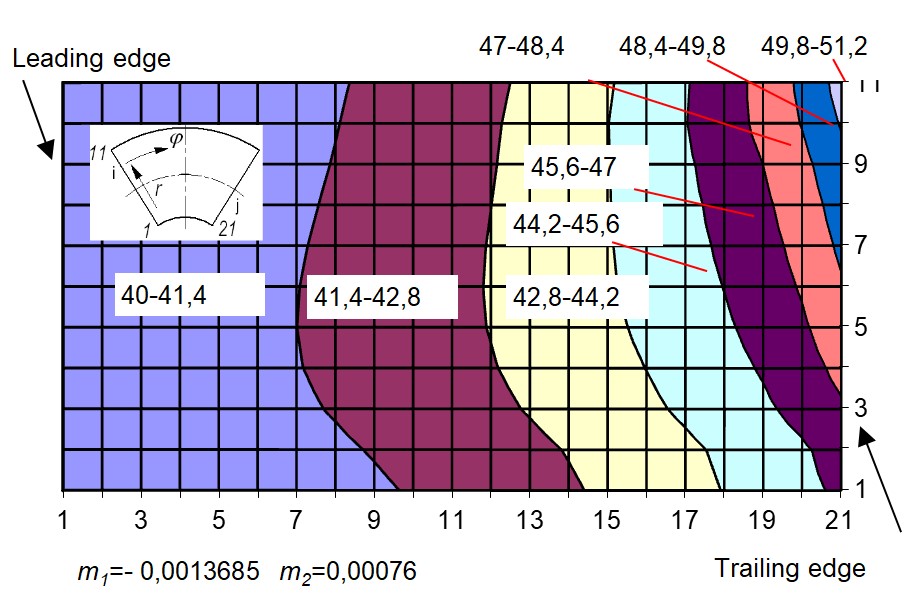
Figure 9 - Isotherms (in 0C) of oil film temperature distribution on the tilting pad
Note: – upper part of temperature field close to the trailing edge
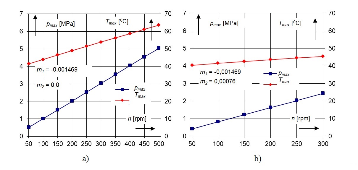
Figure 10 - Maximum oil film pressure and temperature versus different rotational speeds of thrust collar for pad tilt angles:
a – m1 ≠ 0, m2=0; b – m1 ≠ 0 and m2 ≠ 0
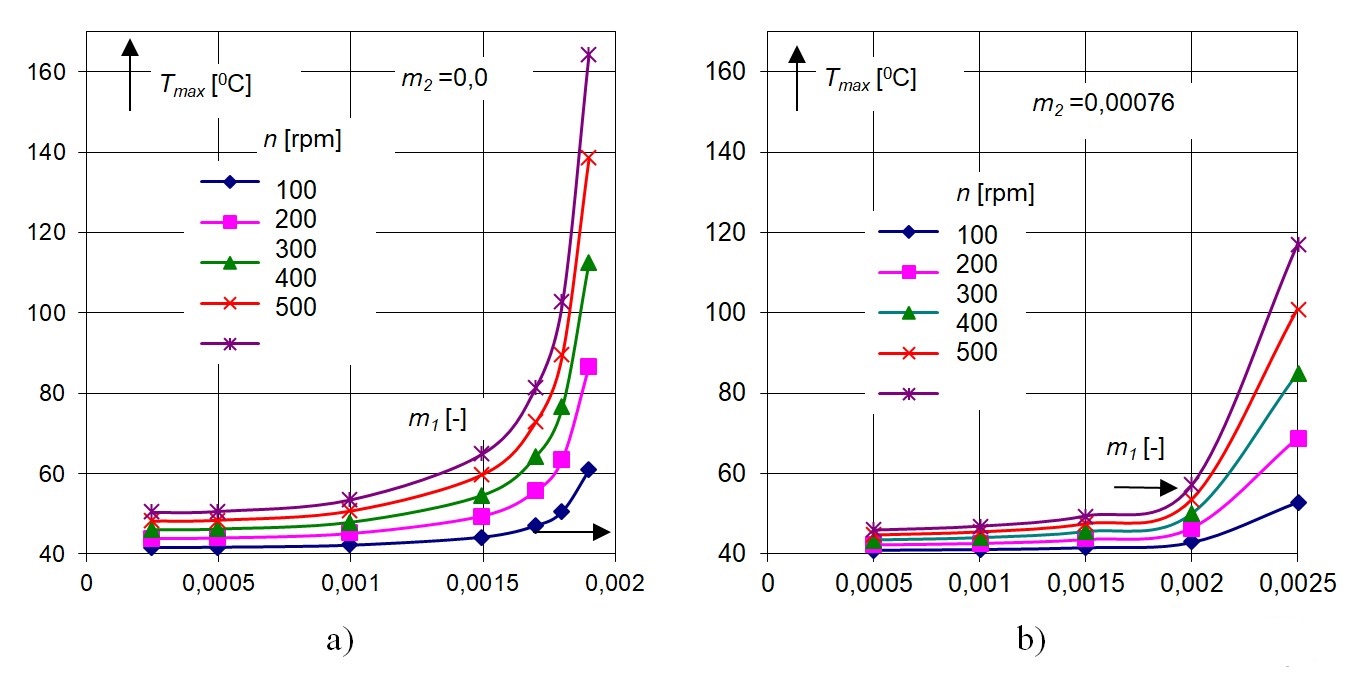
Figure 11 - Maximum oil film temperature versus pad tilt angles m1 and for different tilt pad angles m2:
a – m2 = 0,0; b – m2 = 0,00076
Effect of different rotational speeds of thrust collar on the maximum oil film temperature for assumed pad tilt angles illustrates Fig. 13 (a – constant m1, b – constant m2).
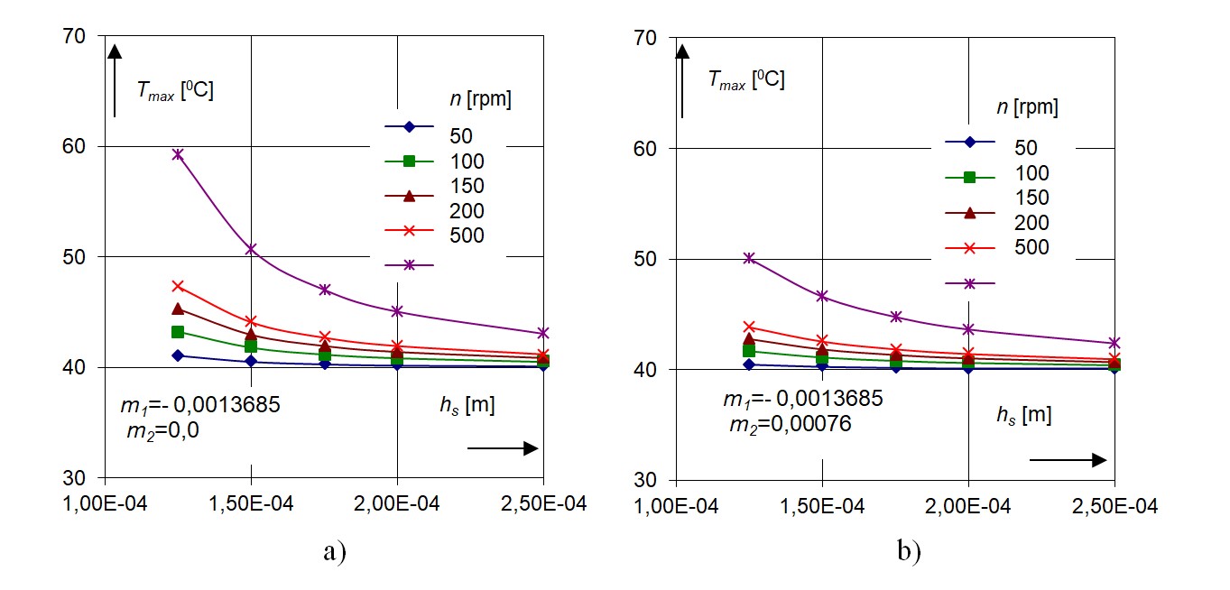
Figure 12 - Maximum oil film temperature versus assumed oil film thickness hs for different rotational speeds of thrust collar at assumed value of m1 and different values of m2:
a – m2 = 0,0; b – m2 = 0,00076
Note: oil film temperature at the pad inlet was Tp=400C
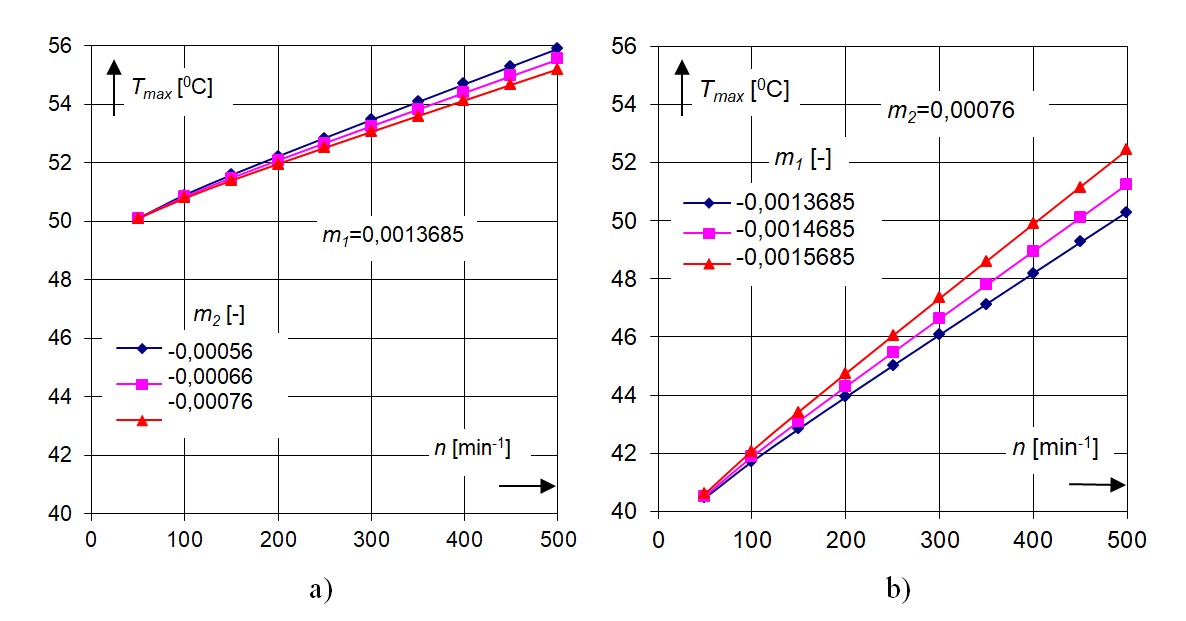
Figure 13 - Effect of rotational speed of thrust collar on the maximum oil film temperature for different pad tilt angles m1:
a – constant m1; b – constant m2
However, when the tilt angle of pad m1 is larger than nil and the angle m2=0,0 then the different run of temperatures is observed (Fig. 15); there is almost no difference in the maximum temperatures of runs for close values of m1 (Fig. 14 the lines 1 and 4). In this discussed case, the maximum temperatures of oil film are lower as compare to the case in which the angles m1 and m2 differ from nil.
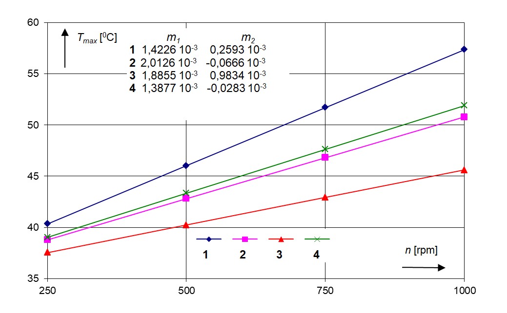
Figure 14 - Effect of different pad tilt angles on the maximum oil film temperature of pad versus rotational speeds of thrust collar
Note: based on [3]
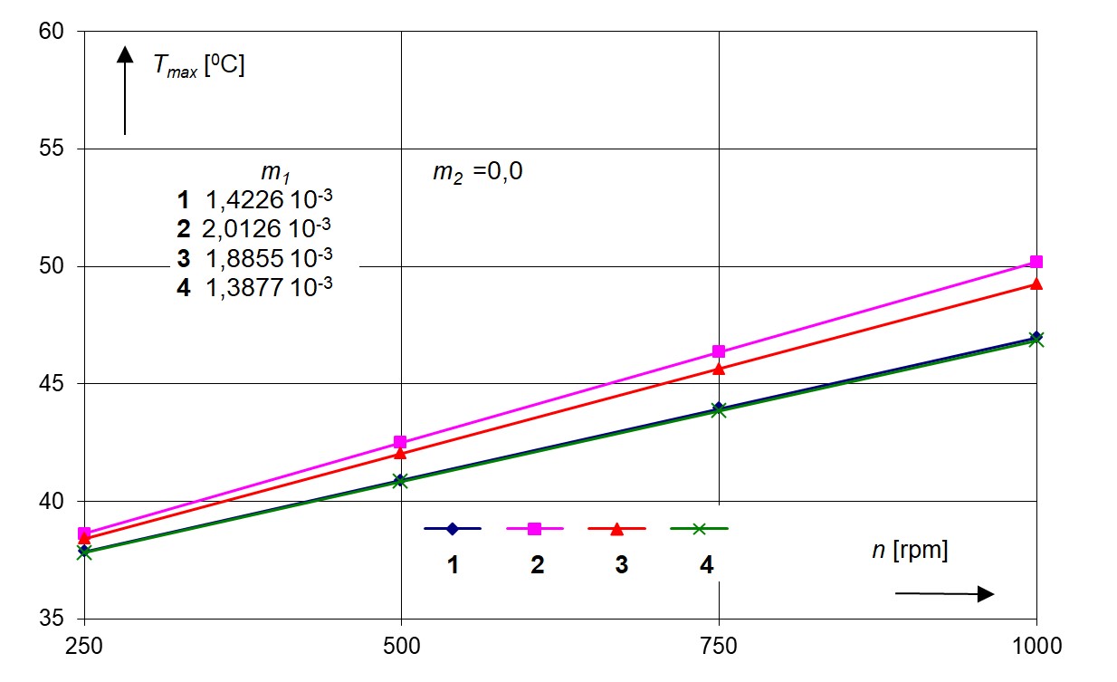
Figure 15 - Effect of different pad tilt angles m1 ≠ 0 at m2 = 0,0 on the maximum oil film temperature of pad versus rotational speeds of thrust collar
Figure 16 shows maximum oil film temperature versus rotational speeds of thrust collar at assumed value of oil film thickness and tilting pad angles.
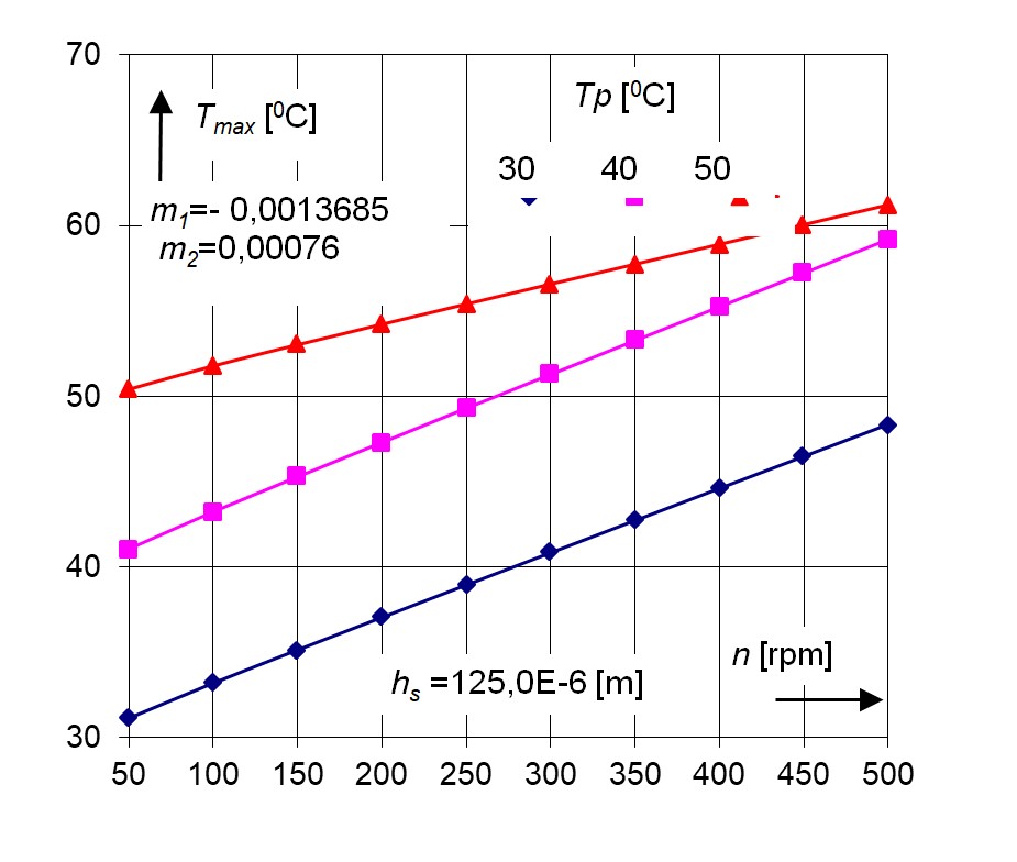
Figure 16 - Maximum oil film temperature versus rotational speed of thrust plate at assumed value of oil film thickness
4. Conclusion
Theoretical calculations and experimental data, as well as the analysis of the results obtained from these studies, allow the formulation of the following conclusions:
1. The geometry of the oil film expressed by the tilt angles of the pad has a significant effect on the operating characteristics of the axial thrust bearing.
2. Pad tilt parameters m1 and m2 at an assumed film thickness at the point of pad support cause the changes in oil film temperature distribution and its maximum values.
3. An increase in the rotational speed of the thrust collar causes the increase in maximum oil film temperature at the increase of pad tilt angles.
4. The isobars and the isotherms of oil film pressure and temperature distribution on the tilting pad point on their maximum value positions, which are placed at trailing edge, upper region of tilting pad.
5. Higher temperatures of supplied lubricant assure smaller increase in its maximum temperatures at the increase in rotational speeds of the thrust plate.
6. A thermocouple controlling the maximum oil film temperature should be placed in the hot spot region of the pad. Such solution is very important for reliable operation of thrust bearing.
In the process of bearing design, it is necessary to take into account two angles of tilt pad and analyse the obtained maximum temperatures of oil film. The results giving higher temperatures of oil film and maximum temperatures should be considered as more extreme case. In such situation, the design of bearing should be more resistant against accidental overriding of permissible temperatures of operation.