РАЗРАБОТКА И ИССЛЕДОВАНИЕ ТРЁХМЕРНОЙ МОДЕЛИ СОПЛОВОГО АППАРАТА ЦЕНТРОСТРЕМИТЕЛЬНОЙ ТУРБИНЫ НА НИЗКОКИПЯЩЕМ РАБОЧЕМ ТЕЛЕ
РАЗРАБОТКА И ИССЛЕДОВАНИЕ ТРЁХМЕРНОЙ МОДЕЛИ СОПЛОВОГО АППАРАТА ЦЕНТРОСТРЕМИТЕЛЬНОЙ ТУРБИНЫ НА НИЗКОКИПЯЩЕМ РАБОЧЕМ ТЕЛЕ
Аннотация
Утилизация теплоты низкопотенциальных источников является одной из актуальных проблем энергетики. Одним из перспективных способов решения данной задачи является использование энергетических установок, работающих по органическому циклу Ренкина (ОЦР) на низкокипящих рабочих телах (НРТ).
Целью работы является создание методики трёхмерного (3D) моделирования соплового аппарата центростремительной турбины, выбранной в предыдущих исследованиях в качестве основного оборудования установки на ОЦР, использующей теплоту геотермальных источников теплоты. В данной турбине использовано низкокипящее рабочее тело, при использовании которого можно получить наибольший КПД ОЦР, что было доказано предшествующими проработками темы. В ходе описанного в статье исследования выбран программный продукт для газодинамического расчёта течения рабочего тела в сопловой решётке методом конечных объёмов и получена картина течения. Кроме того, по результатам расчёта разработана процедура нахождения коэффициента потерь энергии, являющегося одной из важнейших характеристик тепловой эффективности.
Разработанная методика моделирования прошла апробацию при исследовании сопловой решётки конкретной спроектированной центростремительной турбины, показав соответствие полученного коэффициента потерь энергии характерному для решётки рассматриваемого типа. Получена визуализация характеристик потока рабочего тела в решётке.
Разработанная модель соплового аппарата в дальнейшем должна быть дополнена с целью исследования режимов работы в целом проточной части центростремительной турбины.
1. Introduction
One of the urgent tasks of modern energy is to utilize the heat of low-potential sources, which, for example, are geothermal sources, flue gases of boiler or gas turbine power plants. A promising way to use such heat is to create plants operating on low-boiling working bodies (LWB). Such substances are also called organic, and the cycle through which these installations operate is called the organic Rankine cycle (ORC).
At the initial stage of the study of power plants operating according to the organic Rankine cycle, it is necessary to study the influence of the types of working medium on the parameters of the power plant cycle in order to select the optimal LWB for this plant. Work carried out a large-scale study, which determined the effectiveness of the ORC for a large number of working bodies depending on the initial and final parameters and gave recommendations for the choice of working bodies depending on the temperature of the heat source. The authors also calculated the ORC, which uses geothermal steam with a temperature of 100-150 °C as a heat source, for different LWBs, which made it possible to choose a refrigerant as the working fluid of the steam turbine plant – pentafluoropropane R245fa, which provides the highest thermal efficiency of the cycle.
Due to the low flow rates of the working medium, as well as the low power of the installation, according to , it is advisable to use a centripetal turbine to convert the thermal energy of the LWB steam into mechanical work. This solution eliminates the need for partial steam supply in the turbine, as well as simplifies its design. Thus, papers
, present models of a radial-axial turbine for operation in power plants on an ORC.The purpose of this work was to study the operation of the circular nozzle assembly of the centripetal turbine based on the construction of its three-dimensional model, followed by numerical calculation using the finite volume method. The results of the calculation should be the distribution of parameters along the sections of the nozzle screen, as well as at its output, and, accordingly, at the entrance to the impeller. Based on the results of 3D calculation, the energy loss coefficient in the nozzle guide vanes should be determined.
2. Research methods and principles
When designing centripetal turbines, one of the main tasks is to study the flow of the working fluid in the blade grid. The most perfect and relevant way to solve this problem is to consider it in a three-dimensional formulation . To implement this principle, a three-dimensional (3D) model of the nozzle assembly was first developed, the section of which is shown in Figure 1.
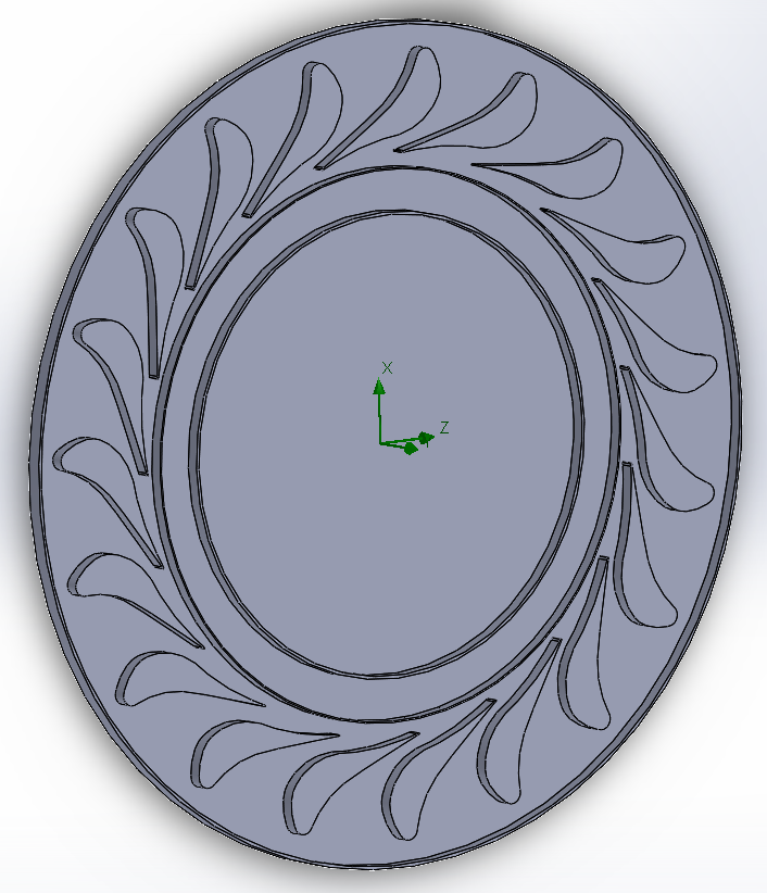
Figure 1 - Section of 3D model of centripetal turbine nozzle guide vanes
FloEFD allows three-dimensional calculations in the field of hydrodynamics, as well as analyzing the characteristics of the heat transfer process
. Thus, this system is a fully functional tool for solving engineering problems in the field of hydrodynamics and heat transfer, built into the main MCAD systems, such as NX, Creo, CATIA V5, Solid Edge and SolidWorks. This software module has more options for performing numerical calculations than the Flow Simulation tool built into SolidWorks, which is a stripped-down version of FloEFD.To create a model of the nozzle guide vanes of the investigated centripetal turbine on the NRT, the condition was used that the impeller diameter d1=0.19 m, and the blade height l1=0.0099 m. The S-9012V profile from the atlas of the Moscow Power Engineering Institute (MPEI) was used as the nozzle blade profile, for the coordinates of which a conformal transformation was applied according to the formulas presented in . The initial profile setting angle was αy=38.27°, and the lattice spacing t=0.33 m. The initial and converted profiles are shown in Figures 2 and 3, respectively.
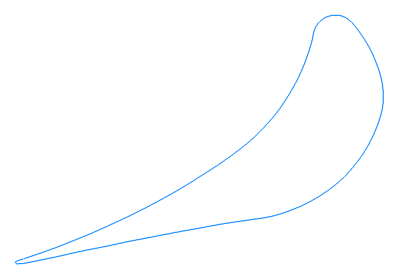
Figure 2 - Initial profile of nozzle blade S-9012V
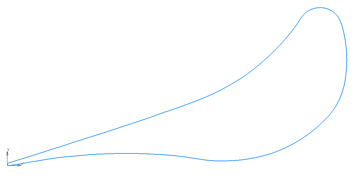
Figure 3 - Conformally mapped S-9012V profile
To create a calculated model, the calculation area shown in Figure 4 was set, and the working fluid was selected - real gas, pentafluoropropane R245fa.
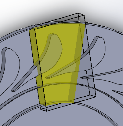
Figure 4 - Calculated model area
The following boundary conditions were applied to the model:
- at the inlet to the design area: total pressure p0*=680000 Pa and temperature T0*=393.15 K determined during the preliminary turbine calculation;
- at the outlet from the design area: static pressure p=277200 Pa determined by iterative method, which corresponds to the pressure downstream the nozzle guide vanes p1=560000 Pa determined during the preliminary turbine calculation.
Type of nozzle guide vanes walls and blades - real wall is specified.
All boundary conditions defined for the generated model are shown in Figure 5.
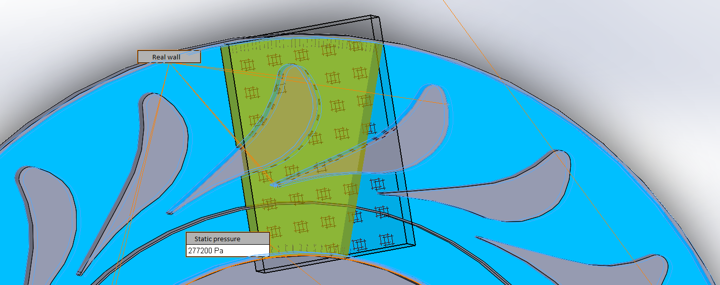
Figure 5 - Model with boundary conditions
It should be noted that manual mesh adjustment was not performed, but the «mesh adaptation» option was selected in order to reduce the use of computing power
.The initial design grid is shown in Figure 6, and the result of the last (third) grid adaptation during the calculation is shown in Figure 7.
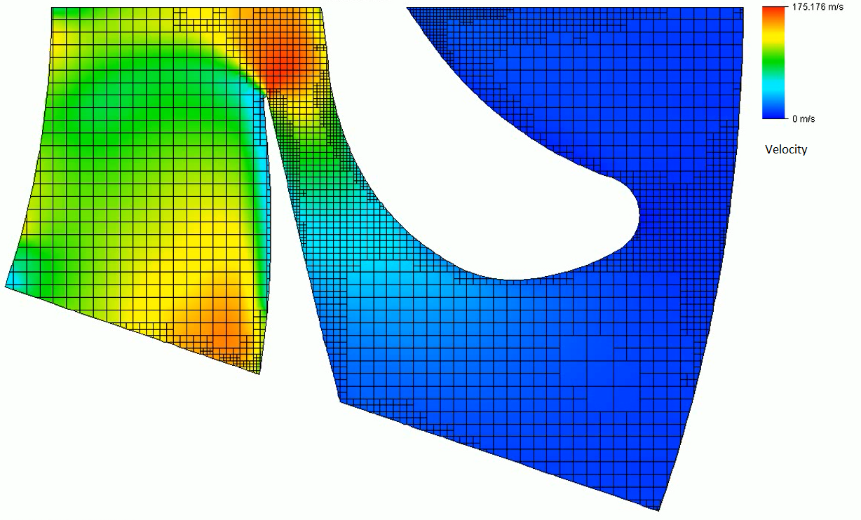
Figure 6 - Initial design grid
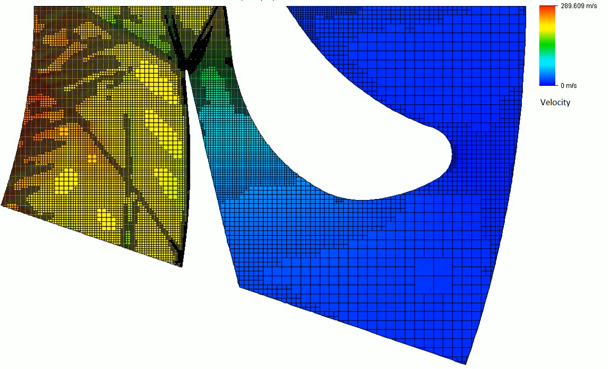
Figure 7 - Third adaptation of the design grid
3. Main results
During the calculation, the program made 1096 iterations, the total number of grid cells after its third adaptation was 2121578, of which 222510 cells can be distinguished on the border with the solid (nozzle vane). The average velocity in the control section at the last iteration took the value 198.53 m/s. The target convergence graph (approximation of the average velocity value to the constant level) is shown in Figure 8.
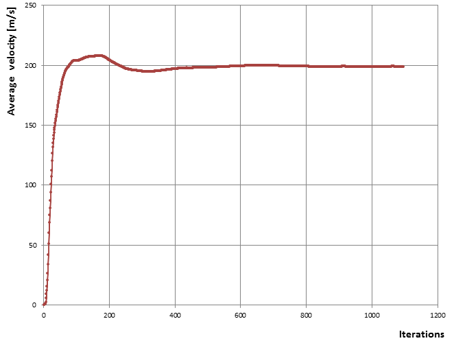
Figure 8 - Target convergence plot
As the results of the model calculation, a picture of the distribution of parameters over the selected section (in the middle of the thickness of the nozzle blade) was built; note here that working medium current lines are displayed. The velocity distribution along the middle section and the line are shown in Figure 9.
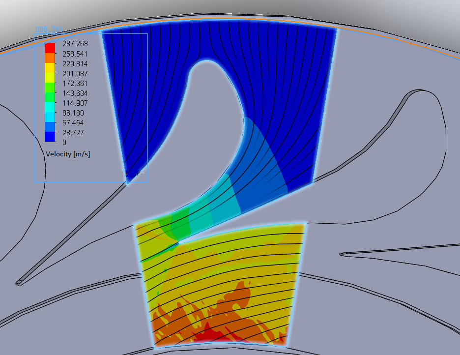
Figure 9 - Picture of velocity distribution and current line in the middle section of the nozzle vane
4. Discussion
The obtained results make it possible to calculate the loss coefficient in the nozzle assembly of the centripetal turbine, which can be determined by the expressions given in
.Enthalpies at inlet and outlet of nozzle guide vanes:
Nozzle exit velocity at isentropic expansion:
Nozzle set loss factor:
To compare the obtained result with the atlas data for the investigated nozzle profile, we determine the Mach number from the theoretical speed c1t:
where is the speed of sound.
Comparing the obtained n loss ratio with the relationships presented in the MPEI atlas for the S-9012V profile, it can be concluded that the obtained value is slightly lower than in the lattice with the original profile (where n = 0.055), which is explained by a more favorable confusor flow in the circular lattice. It should be noted that additional verification of the result of the numerical experiment is desirable by conducting a full-scale experiment for the designed lattice.
5. Conclusion
In the course of the study described in the article, a methodology was developed for building a three-dimensional solid model of the nozzle assembly of a centripetal turbine operating on a low-boiling working fluid. The FloEFD module, which is part of the SolidWorks software product, was selected to calculate and visualize the gas dynamics of the working medium flows when flowing around the nozzle guide vanes. As a result of the work, a 3D model of a circular nozzle assembly of a pre-calculated centripetal turbine was built, and a numerical experiment was carried out to study the gas dynamics of the working fluid flow between the nozzle blades based on the use of the finite volume method. The results of modeling and numerical experiment are the distribution of parameters along the sections of the nozzle grid, as well as their values at the inlet to the impeller, with the help of which the grid loss coefficient was determined, which has a value of n = 0.051.
At the next stage of research, it is planned to use the results obtained during the described work for three-dimensional modeling and determination of gas-dynamic parameters in the flow part of the centripetal turbine as a whole.