Цельностеклянный волоконно-оптический торцевой микротермометр
Цельностеклянный волоконно-оптический торцевой микротермометр
Аннотация
Статья посвящена теоретическому и экспериментальному исследованию цельностеклянного волоконно-оптического микротермометра на основе интерферометра Фабри-Перо. Чувствительная структура, состоящая из трех слоев (оптическое волокно, боросиликатное стекло и среда), изготовлена путем нанесения боросиликатного стекла на расщепленный торец стандартного телекоммуникационного одномодового оптического волокна с помощью микроформовки. Результаты экспериментальных исследований показали, что спектральная чувствительность первого изготовленного образца интерферометра составила 42 пм/°С, а второго 37 пм/°С. Представлена и верифицирована одномерная математическая модель распространения плоской волны через слоистую структуру, позволяющая рассчитать спектральный отклик интерферометра Фабри-Перо с произвольными параметрами структуры. Кроме того, предложенный микротермометр обладает отличной термостабильностью и повторяемостью, что обеспечивает точность измерений температуры в различных условиях.
1. Introduction
High-precision temperature measurement is an important task in various fields of science and technology, particularly in biomedical applications, chemical and food industries, environmental monitoring, and other domains. Fiber-optic temperature sensors offer several advantages over electronic sensors, such as compact size and weight, corrosion resistance, the absence of the need for power supply at the sensing element, immunity to electromagnetic interference, the ability to multiplex sensors and remote placement of recording equipment.
Fiber-optic temperature sensors are currently typically constructed based on Fiber Bragg gratings
or long-period gratings , fluorescence effects , Raman scattering , or interferometers , . The development of interferometric sensors, including temperature sensors, receives significant attention due to the high sensitivity of sensors in this class and the wide variety of their designs. Sensors with the sensing element positioned at the Fiber end face are of particular interest. The operation of such sensors is based on changes in the optical path due to variations in the refractive index of the Fabry-Perot interferometer (FPI) material caused by temperature, as well as due to its thermal expansion (length variation of the interferometer). It should be noted that the relatively small values of the thermo-optic coefficient and the coefficient of thermal expansion of quartz glass, from which the optical Fiber is manufactured, limit the sensitivity of technical solutions that solely use quartz glass to form FPIs. The sensitivity of such elements typically does not exceed ~14 pm/°C . To enhance sensitivity, various materials with increased thermo-optic coefficients and/or thermal expansion coefficients are proposed for use. For instance, in , a silicon cylinder-based Fabry-Perot interferometer (FPI) is presented. This cylinder is fabricated using deep reactive ion plasma etching and attached to the end face of an optical fiber, exhibiting a sensitivity of approximately 85 pm/°C. In an FPI is showcased, created by partially filling a section of hollow fiber with polydimethylsiloxane, resulting in a temperature sensitivity of around 650 pm/°C. A similar approach was demonstrated in , where an FPI was formed in hollow fiber using the polymer adhesive Norland Optical Adhesive 65, cured by ultraviolet exposure, yielding a temperature sensitivity of ~2.87 nm/°C. Common drawbacks of using polymer materials include the need for stabilization and ensuring biocompatibility in biomedical applications. Another example of an FPI with increased temperature sensitivity (~430 pm/°C) involves a sealed cavity within an optical fiber filled with ethanol , although such a sensor is more complex to manufacture.The paper introduces a Fabry-Perot interferometer with enhanced temperature sensitivity, fabricated by depositing borosilicate glass onto the end face of a standard telecommunications single-mode optical fiber using a microforge. The first section of the article presents a mathematical model of the Fabry-Perot interferometer, followed by the second section outlining the fabrication method of the microthermometer based on the optical fiber FPI. The third section presents the results of experimental investigations, and the concluding section provides the conclusions drawn from the study.
2. Mathematical Model of the Fabry-Perot Interferometer
In a general sense, the Fabry-Perot interferometer consists of two coaxial, parallel, and opposing mirrors between which a resonant standing optical wave is formed. In this case, the mirrors are formed by the boundaries between two optically transparent media. The Fabry-Perot model
, can be represented as a structure consisting of three distinct homogeneous layers through which a plane monochromatic optical wave propagates. The refractive index mismatch of the media causes partial reflection of the wave at their interfaces, forming mirrors, which leads to the emergence of interference and resonance. The reflection coefficient of the radiation depends on the thickness of the interferometer-forming layer, the dielectric and magnetic permeabilities of the media, as well as the wavelength of the incident radiation. As a result of passing broadband radiation through the Fabry-Perot interferometer, its amplitude periodically changes depending on the wavelength, resulting in distinct peaks and troughs in the FPI reflection spectrum.By controlling the reflection spectrum and the positions of the maxima of the Fabry-Perot interferometer, it is possible to determine changes in the refractive index (both dielectric and magnetic permeabilities) of the layers constituting the FPI, as well as variations in the interferometer length due to external influences.
The length of a Fiber optic FPI can be comparable to the wavelength of the radiation or much larger than it. The diameter of the optical fiber does not exceed a few tens of wavelengths, and light propagation occurs along the Fiber core. This justifies the application of a one-dimensional mathematical model for the propagation of a plane wave through a layered structure (FPI). The model of such a structure is presented in Figure 1.
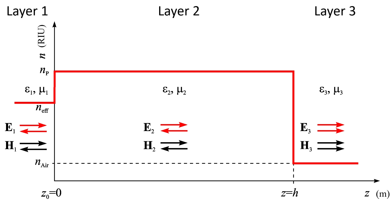
Figure 1 - One-dimensional model of the Fabry-Perot interferometer
The wave number for each medium is defined as:
where, ω – frequency, εi – dielectric permittivity, μi – magnetic permeability of the layer, ε0 – absolute dielectric permittivity, μ0 – absolute magnetic permeability, λ –wavelength. The equations for the electric and magnetic fields in each layer are:
where ti and ri are the transmission and reflection coefficients for the layer, and wi represents the wave impedance given by wi = (μ0μi/ε0εi)−1/2.
The continuity of the propagation of electric and magnetic waves is characterized by the equality of these fields in each of the media at their boundaries. At the first interface, when z = 0:
and at the second boundary, at z = h:
Equations (3) and (4) provide with four equations for six unknown coefficients. This system of equations must be complemented. Let all the radiation that has reached the boundary at z = 0 be completely incident on it (the transmission coefficient through Layer 1 is equal to one), and all the radiation that has entered Layer 3 through the boundary at z = h does not propagate in the reverse direction (the reflection coefficient in Layer 3 is zero):
The complete system of four linear equations with respect to four unknown variables r1, t2, r2, t3 (reflection coefficients of the first and second layers, and transmission coefficients of the second and third layers) can be expressed in matrix form as follows:
Of interest is only r1, which describes the reflection coefficient of the electromagnetic wave propagating in the reverse direction. To determine it, we will transform equation (6) into lower triangular form to obtain the relationship of the reflection coefficient with the length h of the interferometer:
Equation (7) can be supplemented with relationships describing the dependence of the interferometer length and the coefficients of magnetic and dielectric permeability on temperature. It allows modeling the reflection spectrum of the sensitive element within the desired spectral range at given temperatures.
3. Microthermometer Fabrication
Borosilicate capillaries WPI 1B15OF-4
were used for the fabrication of the Fabry-Perot interferometer. Using the Fleming-Brown puller Sutter Instrument P–97 a micro-pipette with an elongated tip was drawn from the capillary, which served as the precursor for attaching the sensor to the optical fiber. The puller includes a heating chamber, which facilitates localized heating of the glass capillary. Simultaneously, tension is applied to the ends of the precursor through clamps, causing it to melt and elongate. Depending on the heating temperature, speed, and stretching force, micro-pipettes with desired characteristics can be formed.The micro-pipette was secured onto a microforge constructed according to the Fonbrune design
, which is equipped with a mechanical micromanipulator allowing the movement of the heating filament within the microscope's working area. The heating filament is connected to a transformer, and by adjusting the current, the temperature of the coil can be controlled. Using the sample holder mechanism, the glass precursor's tip can be quickly positioned in the heating filament's area. All operations during the fabrication of micro-tools on the microforge are performed using the heating filament. The glass precursor, in this case, typically remains stationary and should be constantly within the microscope's field of view.In the initial stage, a droplet of borosilicate glass was formed on the heating coil through contact with the heated filament. Subsequently, instead of the precursor, a standard telecommunications single-mode optical fiber SMF-28 was fixed in the sample holder, and a Fabry-Perot interferometer was formed on its end face using borosilicate glass. By adjusting the temperature and manipulating the molten glass with the coil, interferometers of various shapes and geometric dimensions can be formed. Thus, two samples of end-face Fabry-Perot interferometers made from borosilicate glass were fabricated, as depicted in Figure 2, differing from each other in the interferometer length.
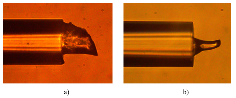
Figure 2 - Microphotographs of fabricated borosilicate Fabry-Perot interferometer samples:
a — Sample 1; b — Sample 2
4. Experimental investigation of the microthermometer
The experimental investigation of the fabricated microthermometer samples was conducted using a drying oven model СМ 50/250-250 ШС produced by LLC "SPM Klimat", The spectral response of the samples was registered using a fiber-optic interrogator based on the Ibsen I-MON-512 spectrometer, which was developed at the RPMT Department of KNRTU-KAI
.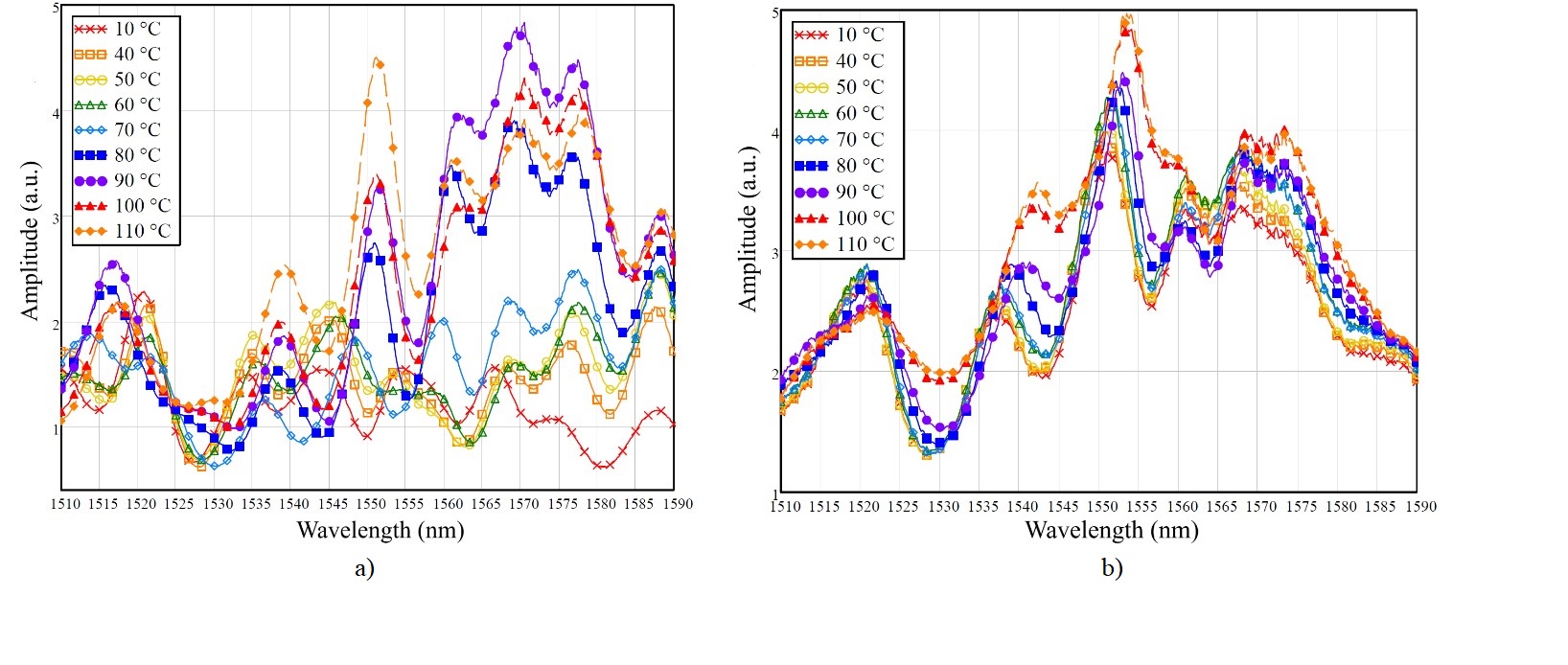
Figure 3 - Spectral responses of the fabricated Fabry-Perot interferometer samples:
a – Sample 1; b – Sample 2
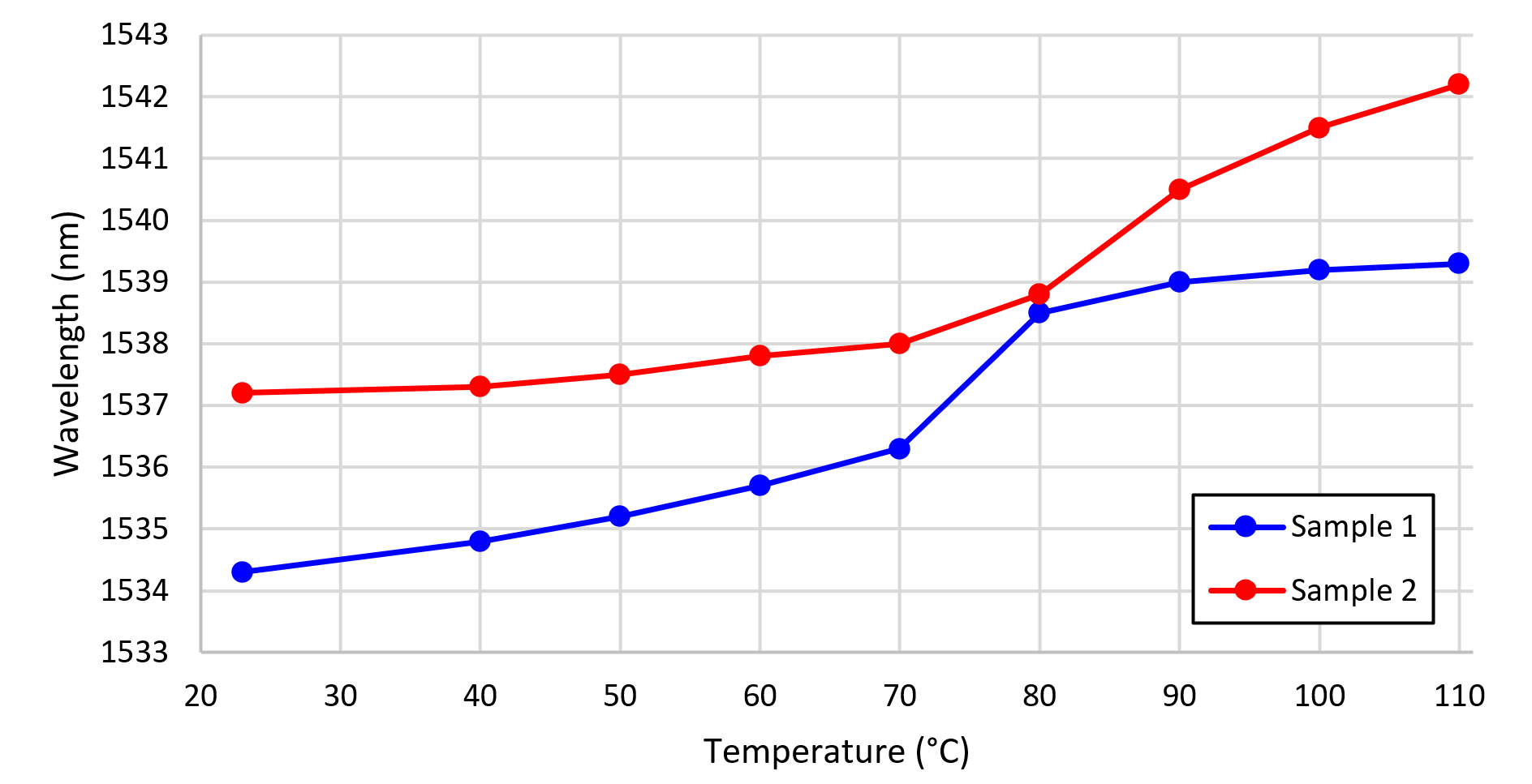
Figure 4 - Characteristics of the peak shifts of the Fabry-Perot interferometer with respect to temperature
Note: blue line –Sample 1, red line – Sample 2
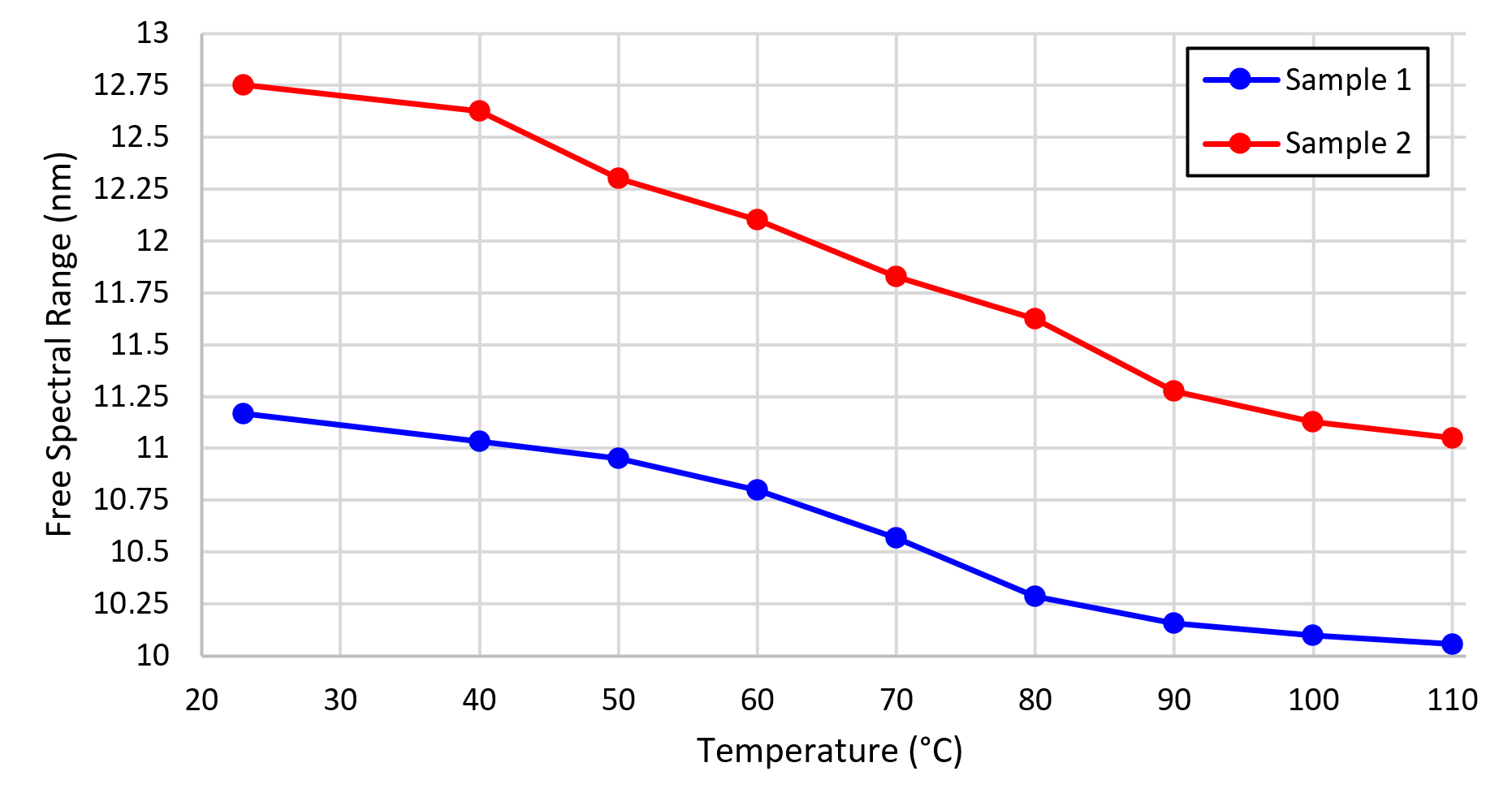
Figure 5 - Dependencies of the free spectral range of Fabry-Perot interferometers on temperature
Note: blue line –Sample 1, red line – Sample 2
To verify the mathematical model of the Fabry-Perot interferometer presented in Section 1, the simulation of the interferometers’ spectral response was simulated, with the parameters corresponding to those of the fabricated samples: interferometer length of 70 μm and 62 μm for the Sample 1 and Sample 2, respectively; interferometer refractive index of 1.4994; optical fiber refractive index of 1.4587; surrounding medium refractive index of 1; optical fiber thermo-optic coefficient of 8.6 × 10⁻⁶ K-1; interferometer thermo-optic coefficient of 17.2 × 10⁻⁶ K-1; interferometer thermal expansion coefficient of 6.3 × 10⁻⁶ K-1.
The calculated spectral responses of the models for both Fabry-Perot interferometer samples made of borosilicate glass are presented in Figure 6 at an ambient temperature of 23 °C.
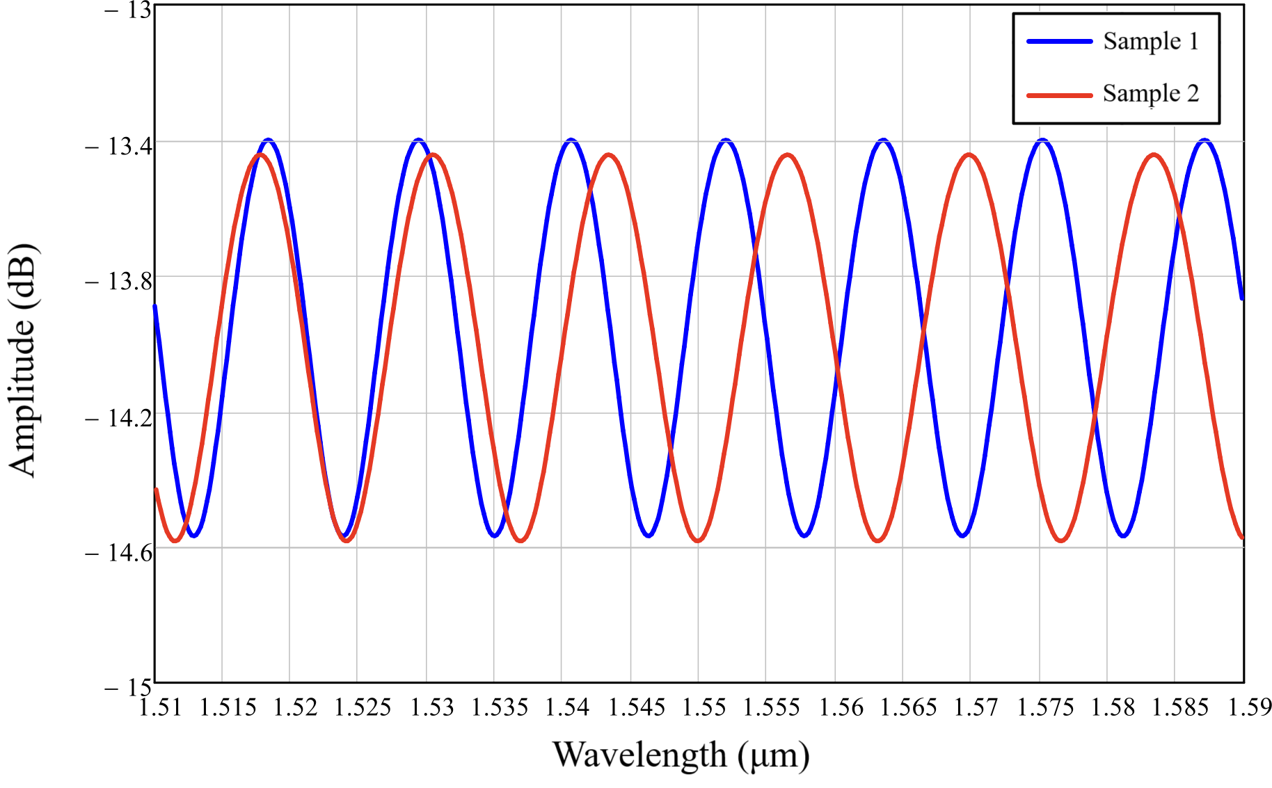
Figure 6 - Spectral reflection responses of the Fabry-Perot interferometer models at a temperature of 23 °C
Note: blue line –Sample 1, red line – Sample 2
5. Discussion
Nowadays, technological advancements impose increasingly demanding challenges in the field of measurement systems. In this context, the development of compact, lightweight, and thin sensitive elements not only become relevant but also critically significant. Fiber-optic sensors, in particular, exhibit substantial potential for addressing metrological tasks, including temperature measurement. Sensitive elements of fiber-optic measurement systems, based on the principles of light propagation through various structured elements within the optical fiber, seemingly align with the requirements of non-invasive measurements. Nevertheless, a range of scenarios exists where the end-face of the optical fiber proves to be excessively large, and its contact with the measurement object leads to uncontrolled dissipation of heat. This is especially important in scientific experiments, where measuring the temperature of an object is an important parameter, and it is undesirable to make changes to its thermal balance in order to avoid distortion of the results. Concurrently, it is essential to acknowledge that employing a fully glass-based optical sensitive element as a temperature sensor stems from the advantages intrinsic to glass, such as its nearly complete chemical neutrality, electromagnetic immunity across a broad frequency spectrum, biological compatibility, and the elimination of the need for electrical power supply. Thus, the challenge of designing a thinner sensitive element for the optical fiber temperature sensor appears to be relevant.
One of the ways to solve the problem is the development of sensitive elements similar to the proposed one, for example, at the end of an optical fiber with a preliminarily reduced diameter so that the diameter of the sensitive element (for example, made of borosilicate glass, Figure 2) coincides with the diameter of the fiber itself. To do this, the optical fiber can be pre-treated. For example, the cladding of an optical fiber may be chemically etched beforehand. To do so, a fragment of an optical fiber is placed in hydrofluoric acid and then is cleaved off. The second possible way to reduce the diameter of the fiber is to heat it and draw it, for example, using a coupler machine or modern welding machines. The thinner end of the optical fiber has a lower heat capacity and has less impact on the measurement object. The authors intend to continue their efforts in this direction.
6. Conclusion
The proposed Fabry-Perot fiber-optic interferometer based on borosilicate glass can serve as a temperature sensor. The fabrication process of such a sensitive element involves creating a micro-pipette from a capillary using a puller, followed by melting it and applying borosilicate glass onto the end of a single-mode optical fiber. The results of experimental studies on the two fabricated interferometer samples demonstrated that both samples exhibit close temperature sensitivity of spectral responses, which is significantly higher than the sensitivity of interferometers based on quartz glass. Specifically, the sensitivity of peak shift to temperature for sample 1 was approximately 42 pm/°C, and for sample 2, it was around 37 pm/°C. A mathematical model of the interferometer based on the scattering and transfer matrix method is presented, which allows calculating spectral responses of interferometers with any predefined parameters. The simulation results are consistent with experimental data and confirm the validity of the proposed model. Among the advantages, the sensor exhibits biocompatibility, insensitivity to moisture, and electromagnetic neutrality. The drawbacks of the presented sensitive element include the complexity of ensuring repeatability of the interferometer's geometrical parameters using the existing fabrication techniques. Authors' further research will be directed towards addressing this issue.