Определение факторов, влияющих на общий коэффициент теплопотерь в вакуумном U-образном солнечном тепловом коллекторе
Определение факторов, влияющих на общий коэффициент теплопотерь в вакуумном U-образном солнечном тепловом коллекторе
Аннотация
Вакуумный U-образный солнечный тепловой коллектор является высокоэффективным для солнечных тепловых систем благодаря своей способности работать в широком диапазоне температур. В данном исследовании изучаются различные факторы, влияющие на общий коэффициент теплопотерь, с целью выявления наиболее значимых параметров и детального анализа их влияния. Минимизируя эти эффекты, можно значительно улучшить характеристики солнечного коллектора. Результаты исследования показали, что наиболее существенное влияние оказывает тепловая эмиссионная способность внутренней поверхности внешней стеклянной трубки. При увеличении эмиссионной способности с 0,05 до 1 общий коэффициент теплопотерь повышается на 98,5%. Аналогичным образом, тепловая эмиссионная способность внешней поверхности внутренней стеклянной трубки также играет важную роль: при увеличении с 0,05 до 1 коэффициент теплопотерь повышается на 93,2%. Среди них излучательная способность внешней поверхности внутренней стеклянной трубки оказывает наибольшее влияние на общий коэффициент теплопотерь. С другой стороны, скорость окружающего воздуха оказывает наименьшее влияние: при увеличении с 1 м/с до 10 м/с коэффициент теплопотерь повышается всего на 7,35%. Примечательно, что при скоростях, превышающих 10 м/с, дальнейшего эффекта не наблюдается. Такие параметры, как температура окружающего воздуха, теплопроводность внешней стеклянной трубки и тепловая эмиссионная способность ее внешней поверхности, не оказывают значительного влияния на коэффициент теплопотери.
1. Introduction
The depletion of fossil fuel reserves, coupled with the severe environmental consequences of their overuse, has accelerated the global shift toward renewable energy. Among the most widely adopted alternatives is solar power. A critical component of this technology is the solar collector, which comes in various designs such as flat plate, vacuum U-tube, and parabolic concentrators.
In thermal engineering, applications are characterized by two fundamental parameters: the required thermal power, or heat flux (kW), and the operating temperature (°C). While two systems may demand similar power, their temperature requirements dictate the appropriate solar collector. For instance, flat plate collectors are generally incapable of sustaining temperatures beyond 100 °C, as their absorbing surface is also the primary site for ambient heat loss. Conversely, vacuum U-tube solar thermal collectors can achieve temperatures upwards of 200 °C. This superior performance is enabled by a vacuum pressure surrounding the absorber tube, which drastically reduces convective thermal losses.
As depicted in Fig. 1, the vacuum U-tube collector consists of an outer glass tube and an inner absorber tube coated with a selective surface. This coating maximizes the absorption of solar radiation and its conversion into thermal energy. The generated heat is partitioned into useful energy, which is transferred to the working fluid, and thermal losses dissipated to the environment. Consequently, the useful energy rate, Qu, can be expressed by equation (1) , .
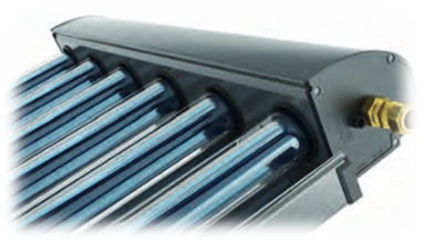
Figure 1 - The evacuated U-pipe solar thermal collector
Note: source [3]
Numerous studies have been carried out to investigate the thermal efficiency and performance of solar thermal collectors. Deshmukh K. experimentally studied the heat transfer performance, pressure drop, and efficiency of a vacuum U-tube solar thermal collector. The stability and thermo physical properties of TiN nanofluid were also measured experimentally. Findings indicate that combining 0.1% TiN nanofluid with a twisted tape (H/D = 5) enhances the convective heat transfer coefficient by 68.9% at a flow rate of 1.25 liters per minute (LPM) compared to water at 0.25 LPM. Under identical conditions, the pressure drop increased by 88.5%. The performance of the solar thermal collector with TiN nanofluid reached 98.66% and 71.53% at a 0.1% volume concentration, with and without twisted tape, respectively.
Avezov R.R. developed a methodology for calculating the heat loss coefficient through translucent coatings in flat plate collectors, accounting for the effects of partial radiation absorption and heat transformation. The proposed formula was demonstrated with a practical computational example.
As part of a parametric analysis, Senthil R. determined that the thermal performance of a parabolic dish receiver is highly dependent on environmental conditions and material properties. While wind speed exacerbates convective losses, higher ambient temperatures reduce the system's thermal capacity. A critical finding was that reducing the emissivity of the receiver coating from 0.9 to 0.2 resulted in a 75% reduction in heat losses, underscoring the paramount importance of surface coating optimization.
In further work, Avezov R.R. quantified the heat loss coefficient for absorbing panels in flat-plate collectors, evaluating the distinct influences of both free and forced convection and analyzing the temperature dependence of the convective and radiative loss components.
Kumar A. performed a thermodynamic comparison of flat plate and vacuum tube collectors, identifying absorber plate temperature as the most significant factor governing heat loss. The study concluded that minimizing this loss requires maintaining the absorber temperature close to the ambient, achievable by increasing the heat transfer fluid's flow rate or its heat capacity through the addition of nanoparticles.
Celik Toker S. developed a mathematical model to simulate the dynamic thermal performance of vacuum U-tube collectors using carbon dioxide (CO₂) as a working fluid for low to medium-temperature applications. Validation against experimental data showed a marginal deviation of 6.3% between theoretical and empirical results.
Tekkalmaz M. numerically demonstrated that the top heat loss coefficient in flat plate collectors is highly sensitive to the glazing material and the collector's tilt angle. Plastic covers (e.g., Lexan, acrylic) were found to exhibit a lower loss coefficient than glass. The maximum heat loss was shown to increase linearly with absorber plate temperature but remained largely unaffected by variations in ambient temperature.
Kiran naik B. experimentally compared a vacuum U-tube collector integrated with a parabolic reflector (EUSCIPR) to a conventional evacuated tube collector (CEUSC). Numerical analysis indicated that the EUSCIPR configuration achieved a 14.1% higher thermal efficiency within the tested operating range, with both systems exhibiting peak energy losses during peak insolation hours.
Moslemi H.R. investigated the thermal performance of a vacuum U-tube collector, concluding that efficiency is enhanced by increasing the thermal conductivity of the filler material located in the gap between the copper fin and the absorber surface.
Ataee S. conducted a numerical study on the energy and exergy performance of a U-pipe vacuum collector with filled layers. The research showed that higher thermal conductivity in the filler layer improves both energy and exergy efficiencies. Exergy destruction was found to be maximized when ambient and inlet temperatures were equal, and exergy efficiency declined from 12% at an ambient temperature of -10 °C to 2% at 35 °C.
Gao Y. formulated a mathematical model to predict the thermal performance of a U-pipe evacuated tube (UpEST) collector, incorporating axial and radial temperature distributions. The model's strong agreement with experimental data confirmed its reliability for analyzing the impact of weather conditions and key design parameters — including tube dimensions, flow rate, heat loss coefficient, and coating absorptivity — on thermal efficiency.
2. Materials and methods
The thermal characterization of a vacuum U-tube solar collector is derived from a first-law thermodynamic analysis, establishing a comprehensive energy balance between the circulating heat transfer fluid (HTF) and the ambient environment. This model integrates key parameters, including collector geometry, thermo physical properties of the HTF, the optical efficiency of the system's selective coatings, and prevailing meteorological conditions.
As depicted in Fig. 2, a steady-state, one-dimensional heat transfers schematic and its analogous thermal resistance network represent a cross-section of the absorber and glass tube assembly. Incident solar radiation, denoted as q̇sol, impinges upon and transits the outer glass envelope. This energy is absorbed by the selectively-coated inner glass tube, converting it into a thermal power source.
This captured energy is subsequently partitioned into two distinct pathways:
- Useful Energy Gain: Energy is conducted through the wall of the inner glass tube (q̇54.cond), and then transferred via radiation from its interior surface to the exterior surface of the absorber tube (q̇43.rad). It is then conducted through the absorber tube wall (q̇32.cond) before being convectively absorbed by the HTF through forced convection (q̇12.con).
Thermal Loss: Energy is radiatively lost from the outer surface of the inner glass tube to the inner surface of the outer glass tube (q̇56.rad). This loss is then conducted through the outer tube wall (q̇67.cond) and finally dissipated to the environment through a combination of natural convection to the ambient air (q̇78.con) and net radiation exchange with the sky (q̇7sky.rad).
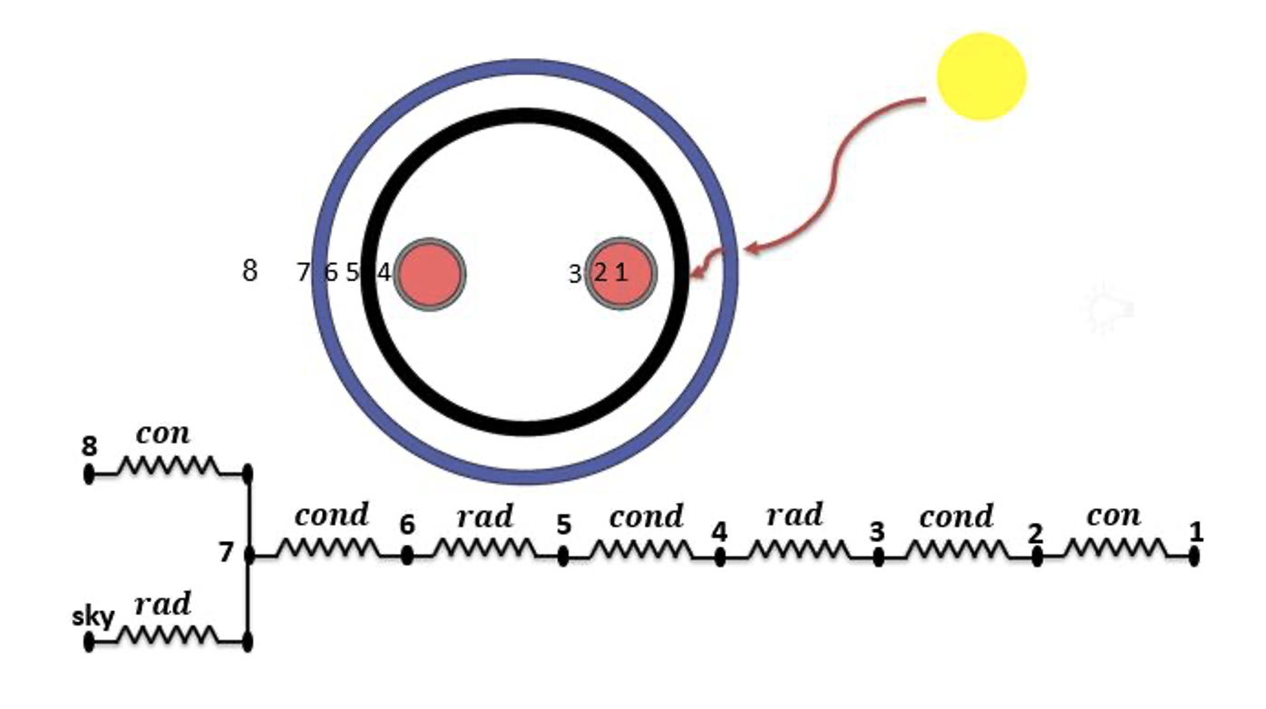
Figure 2 - Cross-sectional view of the absorber tube within the solar collector
This analysis is conducted under the following specific conditions and operational constraints:
1. Geographical and Operational Context:
- Location: The system is simulated for the climatic conditions of Samara, Russia.
- Primary Application: The vacuum U-tube solar thermal collector is designed to power a double-effect absorption refrigeration system with a required thermal capacity of 14.391 kW.
- Target Operating Temperature: The collector must deliver heat transfer fluid (HTF) at a temperature of 140 °C to meet the chiller's operational requirement.
2. Environmental Input
- Solar Insolation: The incident solar flux density is specified as 334 W/m².
3. Collector Configuration and Properties
The design and material properties of the solar collector are defined as follows :
- Installation: Mounted at a fixed tilt angle of 45°.
- Heat Transfer Fluid (HTF): Therminol 66 is employed as the working fluid.
- Glass Tubes:
Inner Tube: Outer diameter = 0.0362 m; wall thickness = 0.0039 m.
Outer Tube: Outer diameter = 0.047 m; wall thickness = 0.0039 m.
- Absorber Tube: Constructed with an outer diameter of 0.008 m and a wall thickness of 0.0005 m.
- Vacuum Condition: The annular space between the inner and outer glass tubes is evacuated, establishing a high-vacuum environment to eliminate convective heat losses.
- Optical Properties:
Glass tube transmissivity (τ) = 0.95.
Absorber tube absorptivity (α) = 0.92.
As previously described, thermal energy is dissipated from the external surface of the inner glass tube to the ambient environment. This heat loss occurs through a series of sequential mechanisms: radiation from the inner glass tube to the interior surface of the outer glass tube (h56.rad), conduction through the wall of the outer glass tube (h67.cond), and finally, from the outer tube's exterior surface to the surroundings via natural convection (h78.con) and radiation to the sky (h7sky.rad).
The overall heat loss coefficient, UL, which quantifies the combined effect of these pathways, is calculated using Equation (2) :
The overall heat loss coefficient UL is derived from the following constituent heat transfer coefficients, each representing a distinct mechanism in the thermal loss pathway.
1. Radiative Transfer Coefficient (h56.rad):
This coefficient quantifies the radiant energy exchange between the exterior surface of the inner glass tube (Surface 5) and the interior surface of the outer glass tube (Surface 6). Its value is a function of the temperatures (T5, T6) and emissivities (Ɛ5, Ɛ6) of these surfaces and is calculated using Equation (3) :
2. Conductive Transfer Coefficient (h67.cond):
This coefficient describes conductive heat transfer through the wall of the outer glass tube, from its interior surface (Diameter D6) to its exterior surface (Diameter D7). It is given by :
3. Convective Transfer Coefficient (h78.con):
This coefficient characterizes natural convection heat loss from the exterior surface of the outer glass tube to the ambient air. It is defined as :
where k78 is the thermal conductivity of air and Nu is the Nusselt number. The calculation of Nu is contingent upon wind conditions, leading to two distinct cases:
Case 1: Forced Convection (Wind velocity Vw = 1 m/s)
The Nusselt number is calculated using the Churchill-Bernstein correlation :
The Reynolds number (Re) is determined by:
The constants c and m are selected from Table 1 based on the calculated Re value. The constant n is defined as:
- n=0.37 for Pr7<=10
- n=0.36 for Pr7>10
Table 1 - Empirical constants c and m for the forced convection correlation
Reynolds number, Re | Constant, c | Constant, m |
1→40 | 0.75 | 0.4 |
40→1000 | 0.51 | 0.5 |
1000→200000 | 0.26 | 0.6 |
200000→1000000 | 0.076 | 0.7 |
Note: source [15]
Case 2: Natural Convection (Wind velocity Vw = 0 m/s)
Under calm conditions, the Nusselt number is modeled using a correlation for a horizontal cylinder :
The Rayleigh number (Ra) is calculated as:
The properties Pr78, α78, and ϑ78 (Prandtl number, thermal diffusivity, and kinematic viscosity of air, respectively) are evaluated at the film temperature T78 = (T7 + T8)/2. The coefficient of volumetric thermal expansion B is approximated for an ideal gas as:
4. Radiative Sky Loss Coefficient (h7sky.rad):
This coefficient defines the radiative heat transfer from the exterior surface of the outer glass tube to the sky. It is expressed as :
Following the establishment of the algorithm for computing the overall heat loss coefficient (UL), the system of implicit equations is solved numerically employing the simple iteration method. This approach is necessary due to the interdependence of surface temperatures and the heat transfer coefficients.
The analysis reveals that the value of UL is predominantly sensitive to the following key parameters:
- The surface emissivity of the exterior of the inner glass tube (Ɛ5).
- The surface emissivity of the interior of the outer glass tube (Ɛ6).
- The surface emissivity of the exterior of the outer glass tube (Ɛ7).
- The thermal conductivity of the outer glass tube material (k67).
- The ambient wind velocity (Vw).
- The ambient air temperature (T7).
3. Results
To ascertain the optimal value of the overall heat loss coefficient (UL), a parametric sensitivity analysis was conducted. The relationship between UL and ambient air velocity is a critical factor, as illustrated in Fig. 3.
The results demonstrate a logarithmic relationship between air velocity and the heat loss coefficient. As velocity increases from 1 m/s to 10 m/s, UL undergoes a significant rise of 7.35%. Beyond this point, the sensitivity of UL to velocity markedly decreases. The increase in the loss coefficient is merely 1.23% between 10 m/s and 20 m/s, and further diminishes to 0.53% between 20 m/s and 30 m/s.
Consequently, it is evident that for wind velocities exceeding 10 m/s, the influence of air speed on the total heat loss coefficient becomes negligible. This finding indicates that design and analysis efforts can prioritize other parameters in high-wind scenarios.
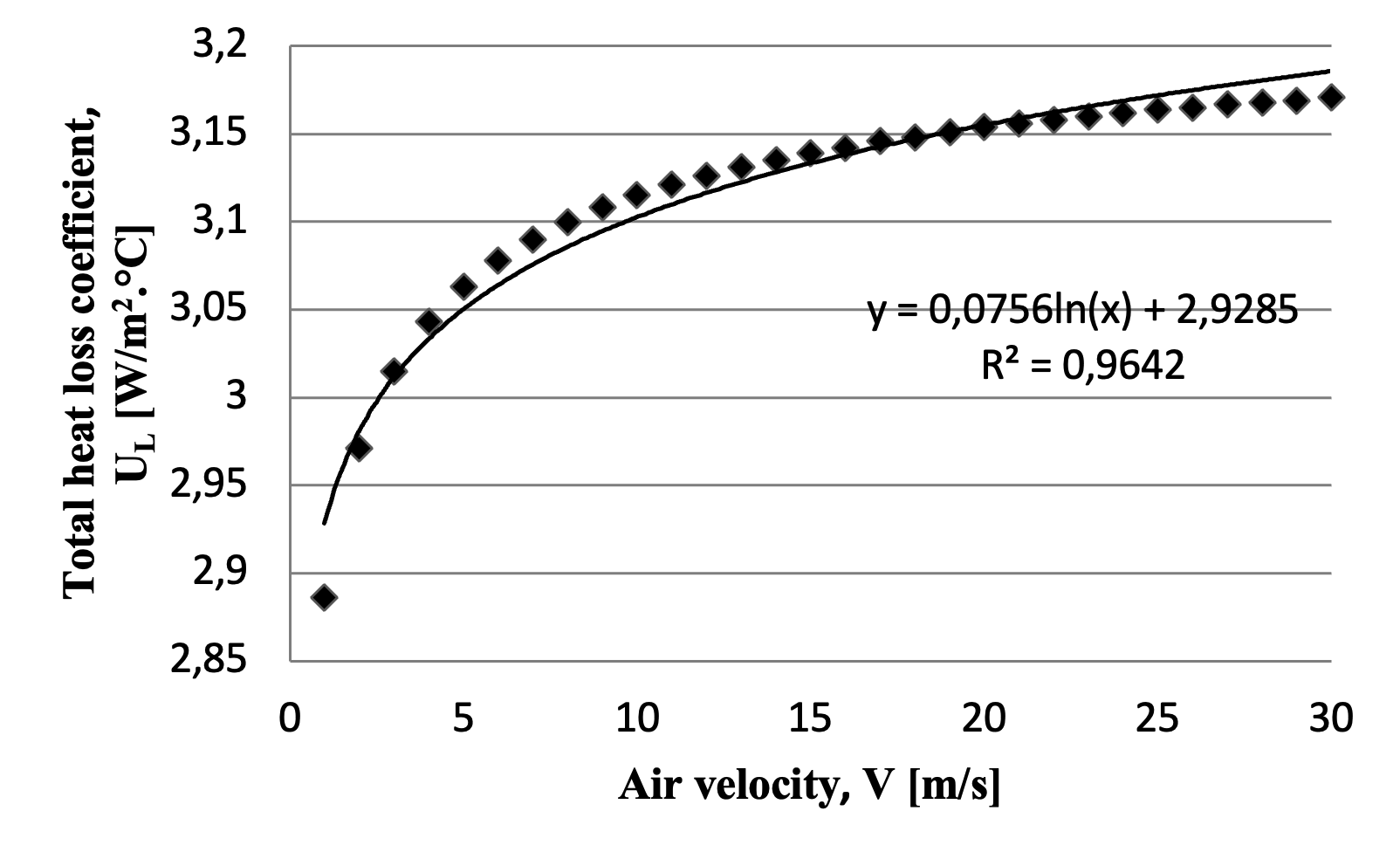
Figure 3 - Variation of the total heat loss coefficient (UL) as a function of ambient air velocity
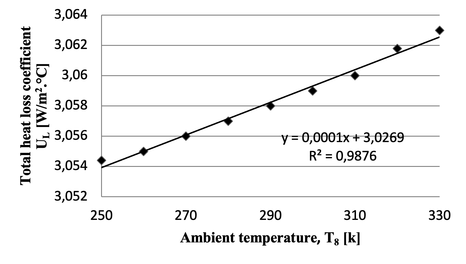
Figure 4 - The total heat loss coefficient varies with changes in ambient temperature
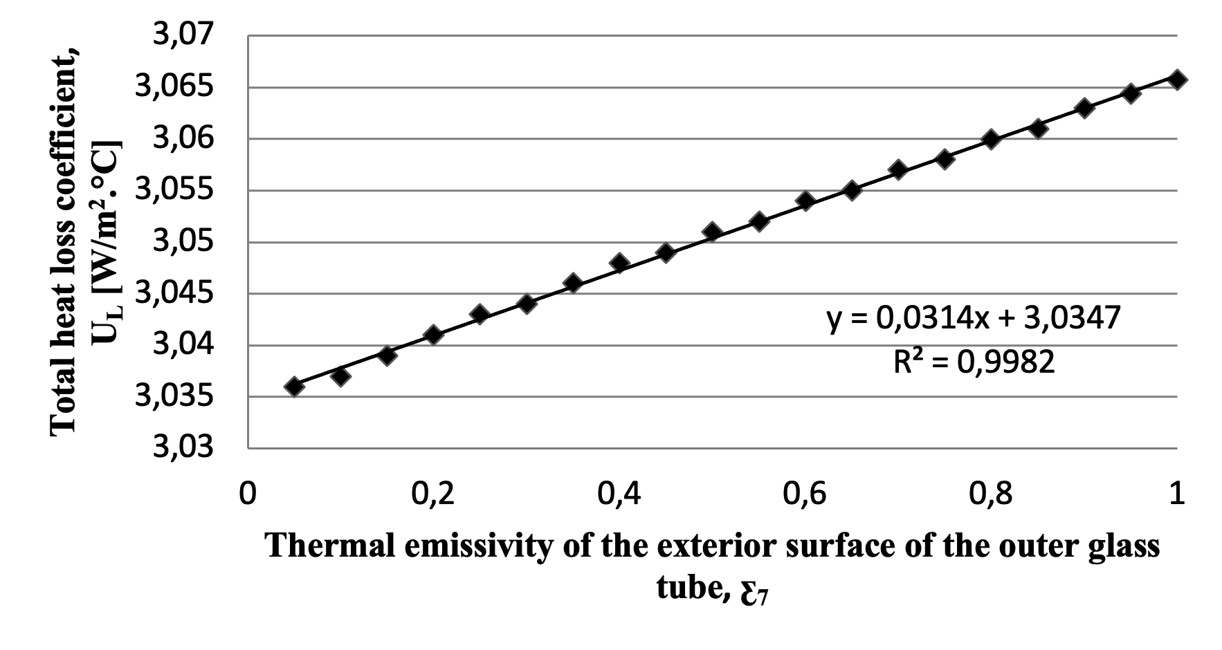
Figure 5 - The total heat loss coefficient varies with changes in the thermal emissivity of the exterior surface of the outer glass tube
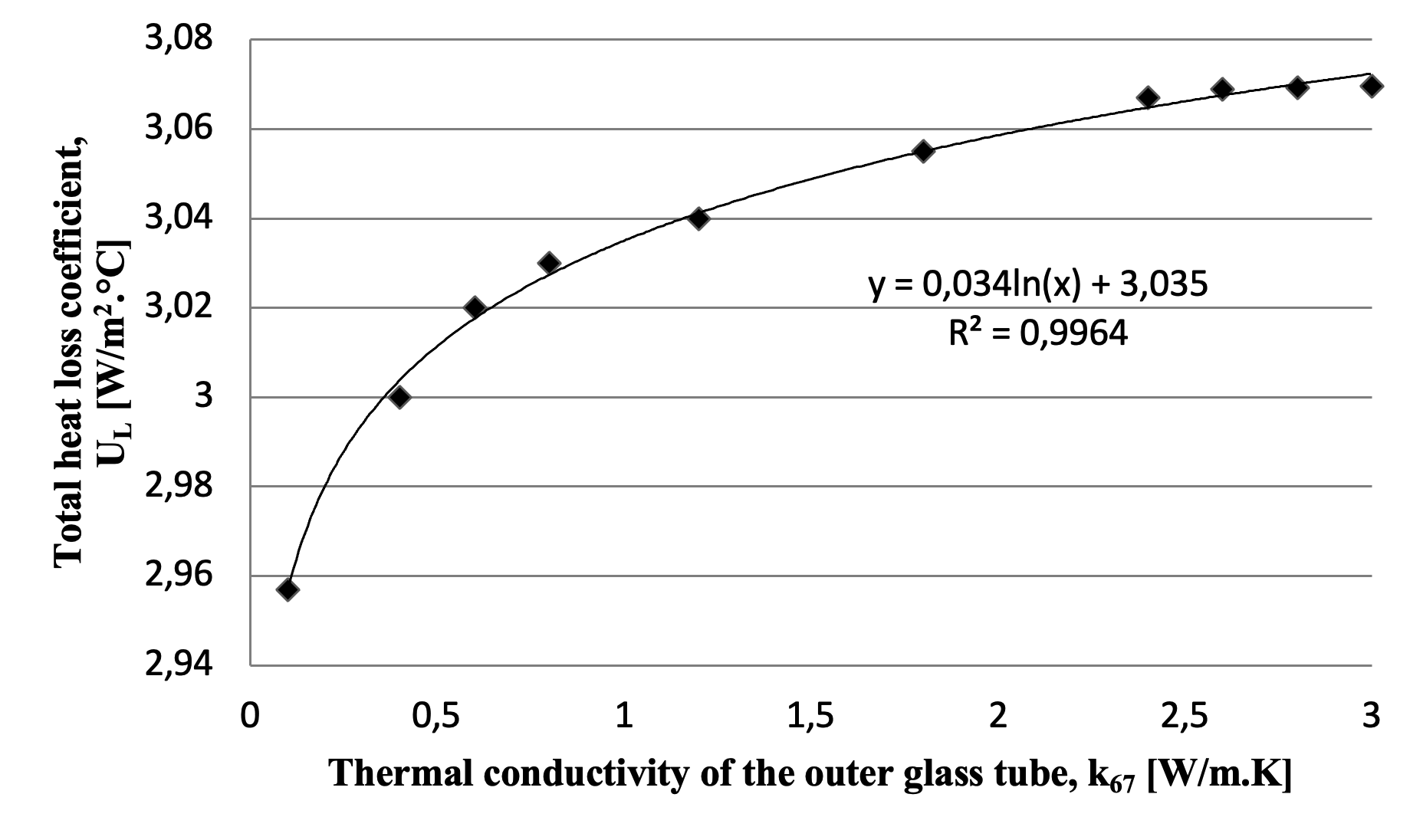
Figure 6 - The total heat loss coefficient varies with changes in the thermal conductivity of the outer glass tube
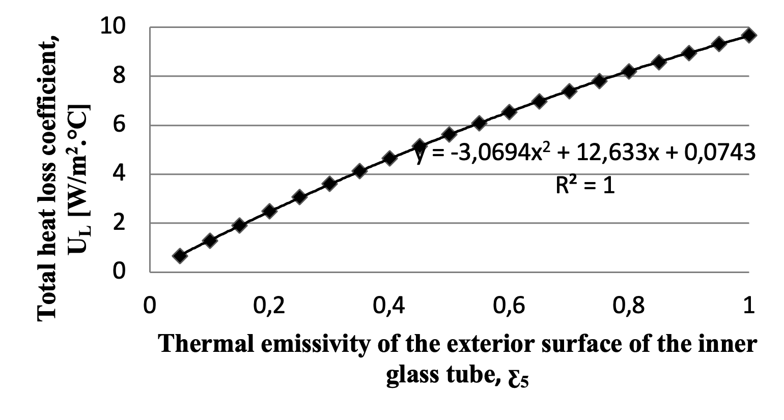
Figure 7 - The total heat loss coefficient varies with changes in the thermal emissivity of the exterior surface of the inner glass tube
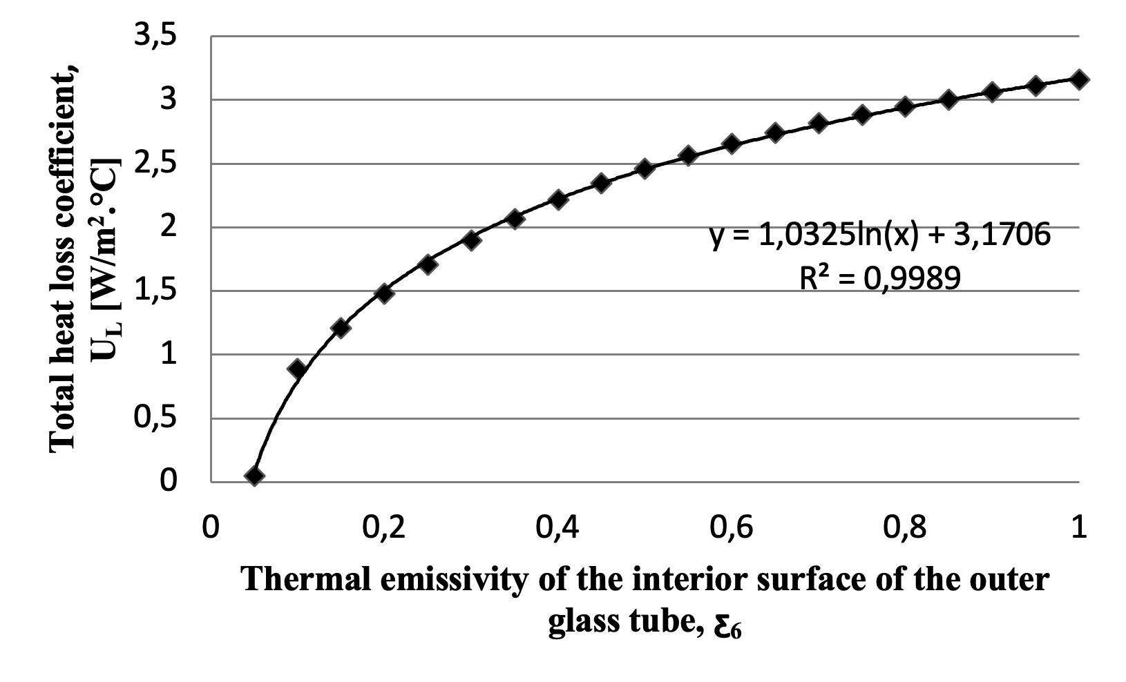
Figure 8 - The total heat loss coefficient varies with changes in the thermal emissivity of the interior surface of the outer glass tube
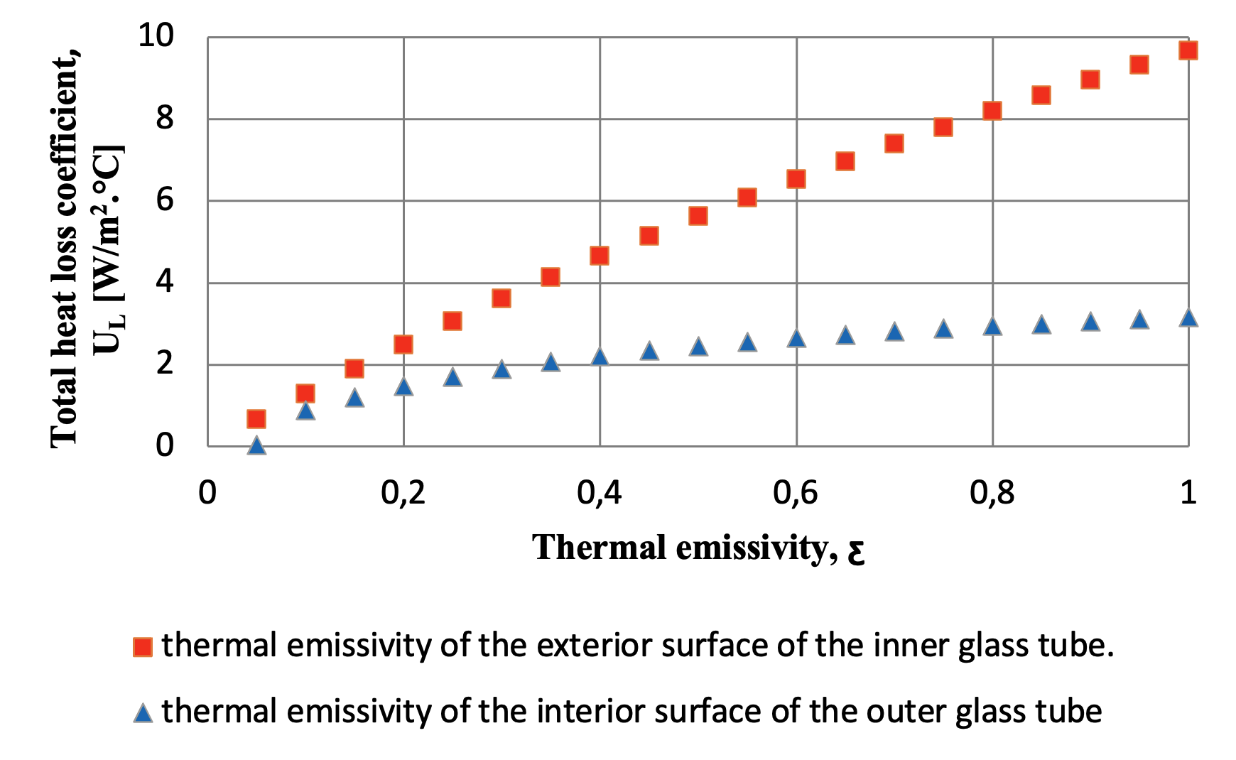
Figure 9 - Comparing the effect of the thermal emissivity between the exterior surface of the inner glass tube (ƹ5) and the interior surface of the outer glass tube (ƹ6) on the total heat loss coefficient
4. Nomenclature
1 — Heat transfer fluid.
2 — Interior surface of the absorber tube.
3 — Exterior surface of the absorber tube.
4 — Interior surface of the inner glass tube.
5 — Exterior surface of the inner glass tube.
6 — Interior surface of the outer glass tube.
7 — Exterior surface of the outer glass tube.
8 — Ambient air.
5. Conclusion
Based on the findings, the thermal emissivity of the exterior surface of the inner glass tube exerts the greatest influence on the total heat loss coefficient. This is a logical outcome, as this surface is the primary site for the absorption of solar radiation and thus a dominant source of heat loss. The emissivity of the interior surface of the outer glass tube also demonstrates a notable, though secondary, impact. In contrast, the thermal conductivity of the outer glass and the emissivity of its exterior surface were found to have a negligible effect.
Regarding ambient air parameters, temperature exhibits a minimal influence, while air velocity has a clear effect, particularly at values below 10 m/s; its influence diminishes significantly at higher speeds.
Key limitation of this study is the assumption of a perfect vacuum between the glass tubes, thereby eliminating convective heat transfer. As this condition is difficult to achieve in practice, it warrants thorough investigation and careful design consideration.
To advance this research, it is recommended to investigate novel selective materials for the critical surfaces (the inner tube exterior and outer tube interior). A comparative analysis of such materials would identify the most effective options for vacuum U-tube solar thermal collectors. Furthermore, the construction of an experimental model is essential to validate these theoretical findings.
The novelty of this work is threefold:
- Comprehensive Parameter Analysis: It systematically identifies all pertinent physical parameters affecting the total heat loss coefficient, as well as those with negligible influence.
- Mathematical Modeling: It derives direct mathematical equations correlating the total heat loss coefficient with its driving parameters.
- Graphical Characterization: It provides detailed graphical curves for each parameter's individual effect.
The theoretical results show strong agreement with prior published works.