МЕТОД ИЗМЕРЕНИЯ ПЛОТНОСТИ РАСПРЕДЕЛЕНИЯ ВОРСА ПО ЗАРЯДАМ, ПОЛУЧЕННЫМ ПРИ КОНТАКТЕ С ЭЛЕКТРОДОМ
МЕТОД ИЗМЕРЕНИЯ ПЛОТНОСТИ РАСПРЕДЕЛЕНИЯ ВОРСА ПО ЗАРЯДАМ, ПОЛУЧЕННЫМ ПРИ КОНТАКТЕ С ЭЛЕКТРОДОМ
Научная статья
Шляхтенко П.
Санкт-Петербургский государственный университет промышленных технологий и дизайна,
Санкт-Петербург, Россия
* Корреспондирующий автор (pavelshl2012[at]yandex.ru)
АннотацияИсследуемый метод относится к методам контроля качества однородных частиц, например частиц ворса, использующихся при нанесении покрытий в сильных электрических полях. Целью настоящего исследования является сокращение времени измерения. Цель достигается благодаря тому, что электрически заряженные частицы рассеиваются в неоднородном электрическом поле, созданном криволинейными электродами, симметричными относительно вертикальной оси. Электрическое поле имеет минимальное значение на этой оси в горизонтальном сечении. Частицы пропускают через отверстие, совпадающее с осью симметрии электрического поля в верхнем электроде, измеряют суммарный заряд на коллекторе, установленном на разной высоте относительно верхнего электрода, и вычисляют функцию распределения заряда частиц. В работе представлены экспериментальные данные, полученные на образце нейлонового ворса, который используют для нанесения ворсовых покрытий методом электровыравнивания. Результаты подтверждают эффективность предложенного метода.
Ключевые слова: электро-флокирование; контроль качества ворса; движение заряженных волокон в неоднородном электрическом поле, симметричном относительно вектора гравитационного поля.
THE METHOD OF MEASURING THE DENSITY OF THE PILE DISTRIBUTION ACCORDING TO THE CHARGES OBTAINED UPON CONTACT WITH THE ELECTRODE
Research article
Shlyakhtenko P. *
St. Petersburg State University of Industrial Technology and Design, St. Petersburg, Russia
* Corresponding author (pavelshl2012[at]yandex.ru)
AbstractThe considered method relates to the methods of quality control of homogeneous particles, such as pile, used when applying coatings in strong electric fields. The aim of the invention is to reduce the measurement time. The goal is achieved by the fact that electrically charged particles are dispersed in a non-uniform electric field created by curvilinear electrodes that are symmetrical about the vertical axis. The electric field has a minimum value on this axis in any horizontal section. Particles are passed through a hole in the upper electrode, which coincides with the axis of symmetry of the electric field, measure the total charge transferred to the collector installed at different heights relative to the upper electrode, and calculate the distribution function of the particle charge. Experimental data obtained on a sample of nylon pile used in applying pile coatings by electro-floating method, which prove the efficiency of the proposed method, are presented.
Keywords: Electro-Flocking; Quality Control of Pile; the Movement of Charged Fibers in a Non-Uniform Electric Field, Symmetric with Respect to the Gravity Field Vector.
IntroductionOne of the main criteria for the quality of a pile coating, obtained by electro-floating, is the bond strength of the pile with the adhesive base, which is largely determined by the kinetic energy of an individual fiber at the adhesive surface. Such energy depends on the specific modes of electro-flocking and increases with an increase in the excess charge on the fiber [1].
It is obvious that the quality of the pile coating to a lesser degree also depends on the magnitude of the statistical scatter of the fibers over the kinetic energies of the adhesive base, which is determined by the density distribution function of the fibers over the excess charges produced by the fibers during their charging. Unfortunately, until the advent of [2], there were no methods and devices for measuring this function.
In Figure 1 shows a diagram of a device [3] that implements the original method proposed in [2].
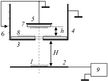
Fig. 1 – Device diagram
The studied fibers 1, which received a charge q in contact with the lower horizontal electrode 2, under the influence of an electric field of intensity E = U / H (where U is the voltage between electrodes 2 and 3) move to the upper electrode 3, acquiring from this electrode kinetic energy Wk. Fibers flying with this energy through the hole in the electrode 3 fall into the Faraday cup 4, where there is no electric field. They continue their inertial motion in the field of gravity, rising to a height that is determined by the value of Wk. A collector 5, mounted at a height h, collects the fibers flying to it, and a pointer 6 registers the height of the collector's location above the upper electrode h.
By measuring under the same initial conditions the number of fibers reaching the collector (Nh), installed sequentially at different heights, we can construct the dependence of the relative number of flying fibers Nh/ N0 on h for a given type of fiber. Differentiating this curve with respect to h, we obtain a normalized curve of the fiber distribution density with respect to this quantity, i.e., the dependence
Then we can write the law of conservation of its energy for the moments of its passage through the hole in the upper electrode and at the point of maximum rise
The total energy spent by the rectifier 9 on the acceleration of the fiber in an electric field between the electrodes 2, 3 is equal to qU.
According to the law of conservation of energy without taking into account the resistance forces of the medium, taking into account (2) it follows:
The elements of the device according to the proposed method have the following design features: electrode 3, cylinder 4 and collector 5 must be under the same potential; the collector 5 is installed above the hole in the electrode 3, coaxially with it and the cylinder 4; the collector's receiving platform should be horizontal; the collector must have freedom of vertical movement, a device for fixing anywhere in the considered interval, and an indicator of the position of the collector's receiving platform above the upper electrode.
In the created device layout, the collector receiving platform 5 is a round metal plate to which a thin interchangeable conductive washer 7 is attached in electrical contact. A layer of liquid glue is applied to the upper and lower surfaces of this washer. On the outer surface of the upper electrode 3 in electrical contact with it, a round removable, adhesive-coated conductive washer 8 is superimposed with a hole corresponding to the hole in the electrode 3. After being kept in the electric field for each measured value of h, these washers with adhered fibers are removed and replaced with new ones.
The total number of fibers is calculated by summing the number of fibers on the collector washer N of the upper electrode. The fiber count was carried out using a microscope.
In Figure 2 shows the experimental curves of the relative number of fibers recorded by the collector versus height h.
In Figure 3 shows the dependences of the distributions normalized to the maximum density over h, , q / m, q for a pile with parameters: D = 50 μm, l = 3 mm, m = 5,2 ×10⁻⁶ g. Scale recalculation along the corresponding abscissa axes was carried out according to formulas (4.22), (4.26), (4.27). The experiment was carried out at U = 7 kV and a constant relative humidity of 100%.
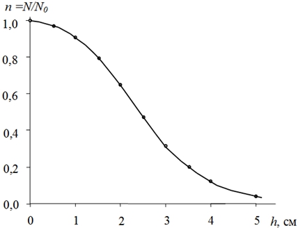
Fig. 2 – Dependence of N / N0 on h
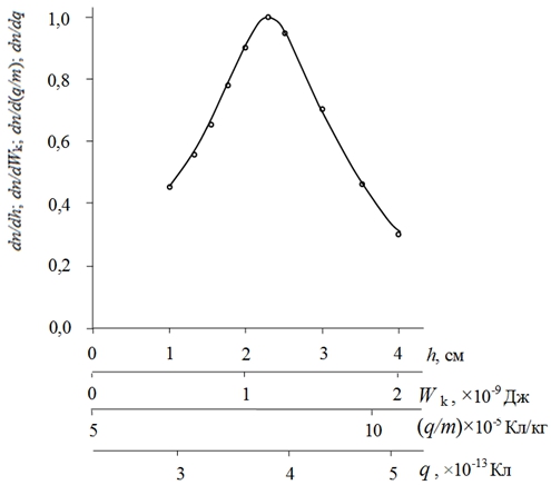
Fig. 3 – Density distribution functions of the pile over the rise height above the upper electrode (h), the kinetic energy of the fiber at the upper electrode (Wk), the specific charge on the fiber (q / m), the charge on the fiber (q) obtained by contact with the lower electrode
The disadvantage of the method [2] is the methodological difficulties and the duration of the counting of villi fixed on the washers 7 and 8 under a microscope.
Results This difficulty was overcome in the method proposed in [6] and described in [5]. In Figure 4 shows a diagram of a device according to this method, work on which proceeds as follows.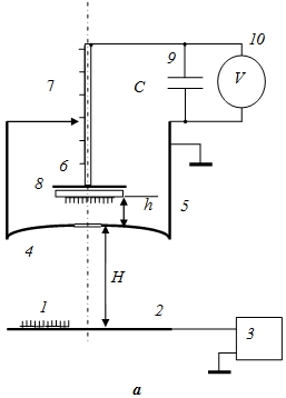
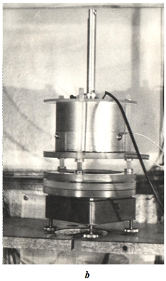
Fig. 4 – Diagram of the device (a) and the appearance of the measuring cell (b)
The fibers reaching the collector at the collector height above the upper electrode h are fixed in the same way using a thin adhesive washer 8, which transfers the excess charge of these fibers Q to a capacitor with a capacity of C (9). The voltage U on the capacitor is measured using an electro-static voltmeter 10, which is associated with the resulting charge by the formula
where Cp is the parasitic capacitance of the installation.
After that, the rectifier 3 is turned off. A new collector height is set above the upper electrode and the entire measurement cycle is repeated.
The advantage of the method under consideration [6] is that the entire fiber sample flies through the hole in the electrode 4, which makes it unnecessary, like the washer 8 in Figure 1 in the method [2], and the operation of counting the villi under the microscope on the washer 8 of collector 6 (Figure 5) in the method under consideration.
In Figure 5 shows the experimental dependence of Q / Q0 on h normalized to unity, obtained for a nylon pile with parameters: D = 50 μm, l = 3 mm, m = 5.2 × 10⁻⁶ g on the device in Figure 4.
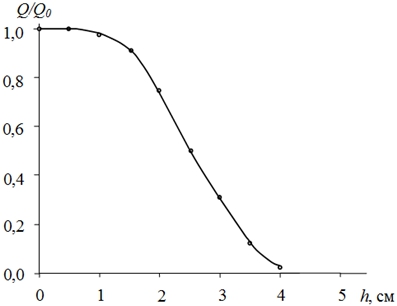
Fig. 5 – The dependence of Q / Q0 on h
In Figure 6 shows the normalized dependence of 1/Q0 ×dQ/dh on h obtained by graphical differentiation of the dependence shown in Figure 5. From formula (6) it follows![]() (12)
(12)
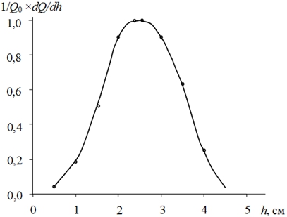
Fig. 6 – Dependence 1/Q0 ×dQ/dh on h
Then the derivative of the dependence presented in Figure 5,Such a distribution calculated by formula (14) and the data in Figure 6 is presented in Figure 7.
Comparison of data Figure 7, constructed by the proposed method, with the data of Figure 3, obtained by the method of [2], shows that these curves are close to each other.
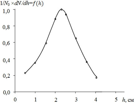
Fig. 7 – Dependence 1/N0 ×dN /dh on h
The desired distribution ![]() can be calculated from the data in Figure 7 using formulas (5), (9) and (10).
can be calculated from the data in Figure 7 using formulas (5), (9) and (10).
In the method under discussion, all fibers reaching the collector are charged by contact with the lower electrode under almost identical conditions. As a result, identical cylindrical fibers would have to receive approximately the same charge, differing only due to differences in the positions of neighboring charging fibers in the immediate environment.
Therefore, the observed significant width of the distributions in Figure 3 and Figure 7 is determined by the author’s opinion by the statistical scatter of the studied villi along the length, diameter [8] and geometry in the region of the fiber cut. It is these parameters, as shown in [5], that determine the amount of excess charge received by the fibers upon separation from the lower electrode.
Conclusion1.On the original device and samples of the synthetic pile used for electroflocking, the efficiency of the method is shown.
2.The time required to obtain one distribution curve by the considered method is two hundred times less than when using the method described in the prototype [3].
3.The discussed method can be used to control any identical quasi-dielectric particles used for coating in an electrostatic field.
| Конфликт интересов Не указан. | Conflict of Interest None declared. |
Список литературы / References
- Бершев, Е.Н. Электрофлокирование / Е. Н. Бершев. – М.: Легкая индустрия – 1977 - 232 с.
- А.с. № 740292 (СССР). МКИ2 в 05 в 5 /02; G 01 N 27/00. Устройство для измерения энергетического распределения волокон при электрофлокировании / П. Г. Шляхтенко и Е. Н. Бершев. Опубл. 15.06.80. Бюл. № 22.
- Шляхтенко П. Г. Измерение распределения ворса по энергиям на верхнем электроде электрофлокатора / Шляхтенко П. Г., Бершев Е.Н. // Изв. вузов. Технология текст. пром., - 1980 - № 6 – С. 34 – 36.
- Шляхтенко П. Г. Движение заряженных волокон в неоднородном электрическом поле / Шляхтенко П. Г., Г. П. Мещерякова.// Электричество – 1991 – №2 – С.54 – 57.
- Шляхтенко П. Полеты ворса во сне и наяву / Шляхтенко П. // Проблемы электрофлокирования: LAP LAMBERT Academic Publishing GmbH & Co.KG.–2016.–192с.
- Патент № 1707524 (РФ) G 01 N 27/60. Способ измерения распределения по зарядам однородных частиц, используемых при нанесении покрытий в электростатическом поле / Шляхтенко П.Г., Нечаев С.А. Опубл. 01.92. Бюл. № 3.
- А.s. № 1024538 (СССР) Н 11/00. Способ получения ворсового материала / Шляхтенко П.Г., Бершев Е.Н., Фирсов Е.И. Опубл. 06.83. Бюл. № 23.
- Семенов В. А. Теория и практика электрофлокирования / Семенов В. А. – М.: ВЗПИ, - 1992 – 151 с.
Список литературы на английском языке / References in English
- Bershev E.N. Elektroflokirovanie [Electro-flocking] / E.N. Bershev. – M.: Light Industry – 1977 – 232 p. [in Russian]
- Patent No. 740292 (SSSR). MKI2 v 05 v 5 /02; G 01 N 27/00. Ustroistvo dlya izmereniya energeticheskogo raspredeleniya volokon pri elektroflokirovanii [Device for Measuring Energy Distribution of Fibers during Electro-flocking] / P. G. Shlyakhtenko and E. N. Bershev. Publ. 06/15/80. Bull. No. 22. [in Russian]
- Shlyakhtenko P. G. Izmerenie raspredeleniya vorsa po energiyam na verkhnem elektrode elektroflokatora [Measurement of Energy Distribution of Pile on Upper Electrode of Electro-flocator] / Shlyakhtenko P. G., Bershev E.N. // vuzov. Tekhnologiya tekst. Prom [Bulletin of Universities. Technology of Text. Industry] – 1980. – No. 6 – P. 34-36. [in Russian]
- Shlyakhtenko P. G. Dvizhenie zaryazhennykh volokon v neodnorodnom elektricheskom pole [Movement of Charged Fibers in Inhomogeneous Electric Field] / Shlyakhtenko P. G., G. P. Meshcheryakova. // Elektrichestvo [Electricity] – 1991 – No. 2 – P.54 - 57. [in Russian]
- Shlyakhtenko P. Polety vorsa vo sne i nayavu [Flight of Pile in a Dream and Reality] / Shlyakhtenko P. // Electro-flocking Issues: LAP LAMBERT Academic Publishing GmbH & Co.KG. – 2016. – 192 p. [in Russian]
- Patent No. 1707524 (RF) G 01 N 27/60. Sposob izmereniya raspredeleniya po zaryadam odnorodnykh chastits, ispolzuemykh pri nanesenii pokrytii v elektrostaticheskom pole [Method for Measuring Charge Distribution of Homogeneous Particles Used for Coating in Electrostatic Field] / Shlyakhtenko P.G., Nechaev S.A. Publ. 01/23/92. Bull. No. 3. [in Russian]
- Patent No. 1024538 (SSSR) N 11/00. Sposob polucheniya vorsovogo materiala [Method of Obtaining Pile Material] / Shlyakhtenko P.G., Bershev E.N., Firsov E.I. Publ. 06/23/83. Bull. No. 23. [in Russian]
- Semenov V. A. Teoriya i praktika elektroflokirovaniya [Theory and Practice of Electro-flocking] / Semenov V. A. – M.: VZPI. – 1992 – 151 p. [in Russian]