РЕЛЕЙНАЯ ЗАЩИТА НА ПЕРЕХОДНЫХ ПРОЦЕССАХ
Тихомиров A. A.1, Соболев Н.В.2, Прахова T.А.3
1ORCID: 0000-0003-2184-6577 доцент, 2ORCID: 0000-0002-3803-7153, магистрант,
3ORCID: 0000-0001-7540-3371, бакалавр.
Петрозаводский Государственный Университет.
РЕЛЕЙНАЯ ЗАЩИТА НА ПЕРЕХОДНЫХ ПРОЦЕССАХ
Аннотация
В статье изучается возможность построения релейной защиты на переходных процессах. В статье рассматривается расчет переходного процесса однофазного короткого замыкания линии Л-398 «Мончегорск» и возможность использования адаптивного терминала релейной защиты. Метод симметричных составляющих используется для расчета ассиметричного короткого замыкания линии Л-398 «Мончегорск». Адаптивный терминал релейной защиты предлагается использовать при реконструкции линии Л-398 «Мончегорск» на Кольской атомной электростанции.
Ключевые слова: адаптивная релейная защита, переходный процесс, короткое замыкание.
Tikhomirov A. A.1, Sobolev N.V.2, Prahova T.A.3
1ORCID: 0000-0003-2184-6577 associate professor, 2ORCID: 0000-0002-3803-7153, Master’s degree student,
3ORCID: 0000-0001-7540-3371, student.
Petrozavodsk State University
RELAY PROTECTION IN TRANSIENT PROCESSES
Abstract
The paper studies the possibility of building relay protection in transient processes. The article considers the calculation of transient processes short-circuit currents for line Л-398 “Monchegorsk” and the possibility of using an adaptive relay protection terminal. A method of symmetrical components is used to calculate the assymetrical short circuit of line Л-398 “Monchegorsk”. Adaptive relay protection terminal is proposed to be used in designing (engineering) reconstruction of Kolskaya Atomic Power Station Л-398 “Monchegorsk”.
Keywords: adoptive relay protection, transient processes, short circuit.
Introduction
In order to protect energy system objects from malfunctions, specifically from short circuit currents, relay protection is used. For reliable protection from short circuit current relay protection has to meet 4 requirements [1, P.10]:
- Selective ability (the ability to cut off only the damaged area)
- Fast response (time during which protection identifies short circuit and cuts off the damaged area)
- Reliability (the ability to response correctly to a malfunction)
- Sensitivity (the ability to respond correctly to all types of malfunctions)
The most important, as well as the most difficult to implement are the requirements of fast response and reliability. The protection is considered unreliable if it performed incorrectly in response to a short circuit or there was a fault in protection operation. This is possible in cases of short circuits that are hard to register, such as non-metallic short circuits and other malfunctions, the current of which does not exceed the set point of relay protection. Apart from that, in case the overall error of a transformer does not exceed 10%, relay protection can respond incorrectly, thus causing great economic loss by damaging electrical equipment, cutting off consumers and causing business interruption.
The idea of building relay protection in transient processes is studied in many scientific articles and literature [2, P. 15]. One of the main ideas in building the protection is using the Fourier algorithm for dividing input signal into orthogonal components and their further analysis [3, P. 81]. Using this algorithm allows to “teach” relay protection to analyze and respond to transient processes of short circuits [4, P 21]. However, Fourier division in relay protection has a limited implementation due to the difficulty in building such protections.
Theoretical part
This article considers the possibility of applying adaptive terminal of relay protection using transient processes of malfunctions in electrical power system in order to enhance reliability and fast response of the protection in simplified representation.[5, P. 107] Considered adaptive terminal of relay protection uses the algorithm for searching the value of input signal and determining its first and second derivative for registration and analysis of a transient process. Dynamics of a transient process and type of electric power system malfunction is defined by the first and the second values of derivatives of peak values. Using this approach allows to avoid using Fourier transform and as a result simplify mathematical calculations. However, such simplification has an impact on protection fast response due to its linkage to peak values.
Terminal scheme is presented in picture 1.
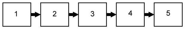
Fig. 1 – Scheme of adaptive terminal of relay protection
- Current and potential transformer
- Measuring element
- Block of dynamic analysis and comparison
- Executive element
- High-voltage circuit-breaker
An input signal is sent from the current and potential transformer 1 to the driving point of the measuring element 2 of the terminal, which goes through analogue-digital processing and arrives at the block of dynamic analysis and comparison 3, where the peak values of voltage and current are:
![]() (1)
(1)
Where Umax is the maximum voltage value in the specified time period, Umin – minimum voltage value in the specified time period.
![]() ; (2)
; (2)
Where I max is the maximum voltage value in the specified time period, I min – minimum voltage value in the specified time period.
After calculating peak values of voltage and current their derivatives are determined:
The first and second voltage derivatives relative to time with defined time interval:
![]() ; (3)
; (3)
![]() ; (4)
; (4)
The first and second current derivatives relative to time with the same defined time interval:
![]() ; (5)
; (5)
![]() ; (6)
; (6)
Values (1)-(6) are compared in pairs with the same data for malfunctions programmed into the block of dynamic analysis and comparison 3 beforehand, which are determined by modelling malfunctions and experimental data received by registration of the abovementioned signal parameters of faults that have already occurred.
When values (1) or (2) are the same with the values set in the terminal’s memory, a signal is generated to the executive element 4, that form a tripping signal for high-voltage circuit-breaker 5. If values (1) or (5) are not reached, but there is an overlap in at least one of values (3)-(6) in time with the data in the memory of the terminal for malfunctions, this value is tracked over time. In case of further overlapping during a specified time period with the data for a malfunction within the determined measurement accuracy, a signal for tripping is produced for a high-voltage circuit-breaker with predetermined time delay, on the basis of a certain type of a malfunction [6, P. 3].
Practical part
We will calculate the transient process in case of a single-phase short-circuit for line Л-398 “Monchegorsk” [7, P.10]. In case of asymmetrical short circuit currents and voltage are different in different phases. Let us assume that a short circuit has appeared in phase A. A method of symmetrical components is used to calculate the assymetrical short circuit [8, P.57]. The main point of the method is that any asymmetrical mode in a circuit can be divided into symmetrical components: direct, inverse and zero sequences. Direct sequence of phase A is equal in absolute value to direct sequence of phase B and is equal in absolute value to direct sequence of phase C. The angle between vectors of direct sequence is 1200. The same rule applies to the components of the inverse sequence. Vectors of the zero sequence are equal, but they are parallel to each other. To calculate the asymmetrical mode it is essential to draw out an equivalent circuit for each of the sequences, calculate their aperiodic component of short-circuit current. In case of a single-phase short-circuit of phase A, the current of phase B and C is equal to zero. The voltage of phase A is equal to zero, and voltage of phase B and C is calculated using a formula:
![]()
![]()
Where Z2 and Z0 – resistances to inverse and zero sequence, IKA1 – short-circuit current in phase A, ![]() ,
, ![]()
To calculate aperiodic short-circuit current of the direct sequence of phase A an equivalent circuit is drawn out (picture 2)
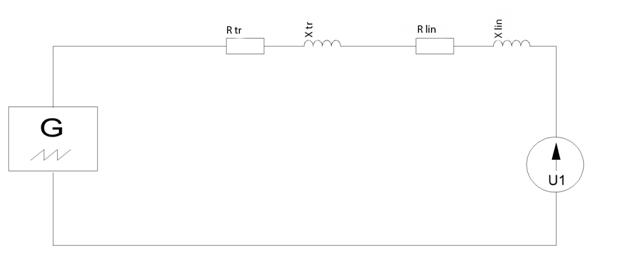
Fig. 2 – Equivalent circuit of direct sequence
By Ohm’s law: ![]() (7)
(7)
We solve the obtained differential equation (7) using Laplace transform,
We obtain:
![]() (8)
(8)
We make a replacement ![]()
Inserting p into (2) we obtain:
![]()
Aperiodic component equals to:
![]() (9)
(9)
Where by Ohm’s law A equals to
![]()
![]()
By inserting A in equation (2) we obtain:
![]() (10)
(10)
Then the full-load current of the direct sequence equals to:
![]() (11)
(11)
Where ![]()
![]() – resistances of direct, inverse and zero sequence.
– resistances of direct, inverse and zero sequence.
We find the resistance of direct, inverse and zero sequences. Source data for calculations are given in [10, P. 35]. Resistance of direct sequence consist of transformer’s, generator’s and line’s resistances. Then the overall resistance of the direct sequence:
![]()
Resistance of inverse sequence consists of transformer’s, line’s and generator’s resistances. Then the overall resistance of the inverse sequence:
![]()
Where generator’s resistance is taken from the generator’s passport, and line’s and transformer’s resistance is equal to the resistance of direct sequence of line and transformer.
Resistance of zero sequence consists of transformer’s, line’s and generator’s resistances. Then the overall resistance of inverse sequence:
![]()
Where generator’s resistance is taken from the generator’s passport, and line’s resistance is equal to 3.5*Xlin1, transformer’s resistance is equal to the resistance of direct sequence of the transformer.
We find IK1:
We bring the current to 330 kW side. Then current IK1 = 410 A
Voltage of direct sequence equals to:
![]()
To calculate aperiodic short-circuit current of the inverse sequence of phase A an equivalent circuit is drawn out (Picture 3)
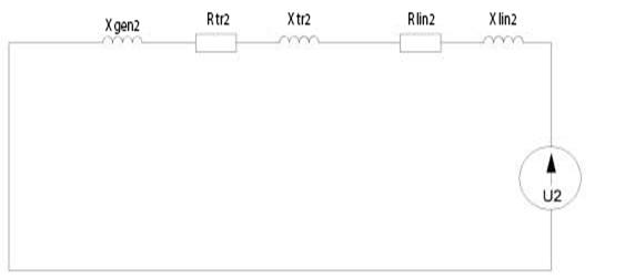
Fig. 3 – Equivalent circuit for inverse sequence
Voltage of inverse sequence equals to [9, P. 90]:
𝑈2 = 𝐼К1 ∗ Z2 = 9 ∗ 0,27 = 2,42 kW
To calculate aperiodic short-circuit current of the zero sequence of phase A an equivalent circuit is drawn out (Picture 4)
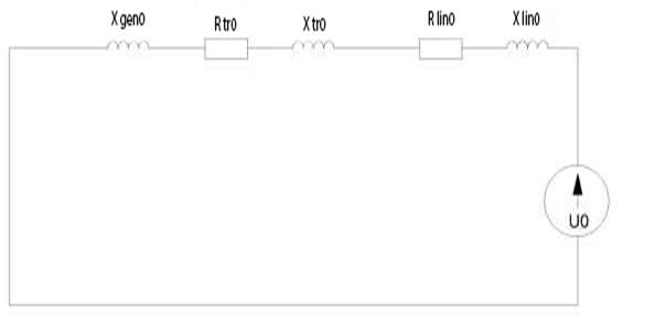
Fig. 4 – Equivalent circuit for zero sequence
Voltage of zero sequence equals to:
𝑈2 = 𝐼К1 ∗ Z2 = 9 ∗ 0,4 = 3,6 kW
𝐼К(1) = 3 ∗ 𝐼К1 = 1230 А
Graph of the transient process of the single-phase short-circuit is given in picture 5.
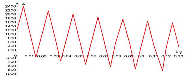
Fig. 5 – Transient process in case of single-phase short-circuit
According to the obtained graph an envelope of the process was plotted. The envelope is given in picture 6.
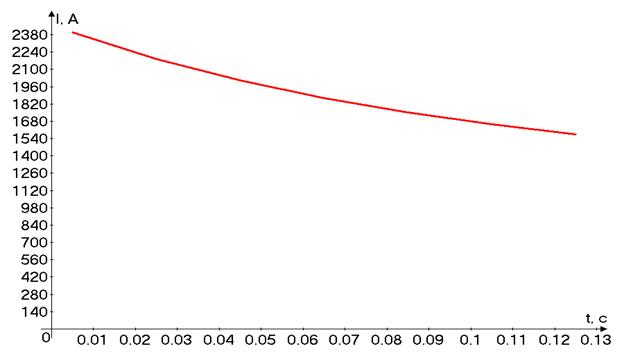
Fig. 6 – Graph of the envelope of the transient process in case of single-phase short-circuit
Conclusion
Using such algorithm allows to implement relay protection terminal for defining dynamic development of electric power system’s malfunctions.
Using such approach allows to build a system of adaptive relay protection without using complicated algorithms. Adaptive relay protection terminal is proposed to be used in designing (engineering) reconstruction of Kolskaya Atomic Power Station Л-398 “Monchegorsk”. The terminal is proposed to be set for responding by the envelope of the transient process of single-phase short-circuit. Using envelopes of transient processes in adaptive terminal of relay protection on the line of Kolskaya Atomic power Station Л-398 allows to indicate the type of short circuit and enhance the reliability of the response of relay protection and the dependence of the current’s surpassing of the short-circuit’s plant is reduced.
Список литературы / References
- Булычев А.В. Релейная защита в электрических системах / Булычев А.В., Наволочный А.А., Поздеев Н.Д. – Вологда, ВоГТУ, 2007. – 154 с.
- Лямец Ю.Я. Обучающиеся релейная защита / Лямец Ю.А., Антонов В.И., Нудельман Г.С. // Электричество – 2012 - № 2 – с. 15-19.
- Лямец Ю.Я. Анализ частотной зависимости характеристик измерительных органов, использующие ортогональные составляющие электрических велечин / Лямец Ю.Я., Ильин В.А. // Электромеханика – 1987 - №10 – с. 81-85.
- Лямец Ю.Я. Оценивание параметров как алгоритм релейной защиты / Лямец Ю.Я., Нудельман Г.С. // Электричество – 199- - №2 – с. 21-24.
- Тихомиров А.А. Использование переходного режима асинхронного двигателя для построения токовой защиты / Тихомиров А.А., Соболев Н.В., Изотов Ю.А. // Международный научно-исследовательский журнал – 2015 - №11 – с. 107-109.
- Пат. 162321 Российская Федерация, МПК H02H 3/40 H 02 J 9/00 Система терминалов релейной защиты / Тихомиров А.А., Соболев Н.В.; заявитель и патентообладатель Петрозаводский Государственный Университет - № 2015146341/07; заявл. 27.10.2015; опубл. 10.06.2016, Бюл. №16. – 6 с.
- Паспорт линии Л-398 “Мончегорск”, Кольская Атомная Электростанция, Росатом, 2001. – с.10.
- Лямец Ю.Я. К анализу переходных процессов в трехфазных цепях методом симметричных составляющих / Лямец Ю.Я. // Электричество – 1988 - №12 – с.57-60.
- Лямец Ю.Я. Обратная последовательность в трехфазной коммутирующей системе / Лямец Ю.Я. // Электричество – 1990 - №9 – с.88-91.
- Бобров А.Е. Электромагнитные переходные процессы в энергосистеме / Бобров А.Е., Дяков А.М., Зорин В.Б. – Красноярск : СФУ, 2009. – 156 с.
Список литературы на английском языке/ References
- Bylichev A.V. Releynaia zachita elektricheskih sistem [relay protection of electrical systems] / Bylichev A.V. Navolochnii A.A. Pozdeev N.D. – Vologda, VSTU, 2007. - 154 p. [in Russian]
- Liamets Iu. Ia. Obuchaychiesya releynaya zachita [Learning Relay Protection] / Liamets Iu. Ia. Antonov V.I., Nudelman G.S. // Elektrichestvo [Electricity. No. 2]. – 2012 - № 2 – P. 15-19 [in Russian]
- Liamets Iu. Ia. Analiz chastotnoy zavisimosti kharakteristik izmeritel'nykh organov, ispol'zuyushchikh ortogonal'nyye sostavlyayushchiye elektricheskikh velichin [Analysis of frequency dependence of characteristics of measuring organs using orthogonal elements of electrical values] / Liamets Iu. Ia., Ilin V.A. // Elektromehanika [Electromechanics. № 10] – 1987 - №10 – P. 81-85 [in Russian]
- Liamets Iu. Ia. Osenivanie parametrov kak algoritm releynoy zachiti [ Parameter estimation as relay protection algorithm]. / Liamets Iu. Ia., Antonov V.I., Nudelman G.S. // Elektrichestvo [Electricity.№. 2]. – 1990 - № 2 – P. 21-24 [in Russian]
- Tikhomirov A.A. Ispolsovanie perehodnogo rezjima asinhronogo dvigatelya dlya postroeniya tokovoi releinoi zachiti [The application of transition mode of asynchronous motor for current protective relay formation] / Tikhomorov A.A., Sobolev N.V., Izotov U.A. // Mejdunarodniy naucho-isledovatelskiy jurnal [International research journal. № 11]. – 2015 - №11 – P. 107-109. [in Russian]
- Pat. 162321 Russian Federation, MPK H02H 3/40 H 02 J 9/00. Sistema terminalov releynoy zachity [relay protection terminal] / Tikhomorov A.A., Sobolev N.V.; the applicant and the patentee Petrozavodsk State University. - № 2015146341/07; appl. 27.10.2015; publ. 10.06.2016, Bul. Number 16. – 6 p.
- Pasport linii L-398 “Monchegorsk” [Passport of the line Л-398 “Monchegorsk”] Kolskya Nuclear Power Station, Rosatom, 2001. – p.10.
- Liamets Iu. Ia. K analizu perekhodnykh protsessov v trekhfaznykh tsepyakh metodom simmetrichnykh sostavlyayushchikh [To the analysis of transient processes in three-phase circuits by the method of symmetric components] / Liamets Iu. Ia. // Elektrichestvo [Electricity. No. 12]. – 1988 - № 12 – P. 57-60 [in Russian]
- Liamets Iu. Ia. Obratnaya posledovatel'nost' v trekhfaznoy kommutiruyushchey sisteme [The reverse sequence in three-phase switching system] / Liamets Iu. Ia. // Elektrichestvo [Electricity. No. 9]. – 1990 - № 9 – P. 88-91 [in Russian]
- Bobrov A.E. Elektromagnitnie perehodnie prosesi v energosisteme [Electromagnetic transient processes in electric power systems] / Bobrov A.E., Diakov A.M., Zorin V.B. – Krasnoyarsk : IPK SFU, 2009. – 156 p. [in Russian]