МАТЕМАТИЧЕСКОЕ МОДЕЛИРОВАНИЕ ТЕМПЕРАТУРНЫХ ПОЛЕЙ ФРАГМЕНТА ФУТЕРОВКИ ТРУБЧАТОЙ ВРАЩАЮЩЕЙСЯ ПЕЧИ
Шариков Ю.В.1, Маркус А.А.2
1Профессор, доктор технических наук, 2аспирант, Национальный минерально-сырьевой университет «ГОРНЫЙ»
МАТЕМАТИЧЕСКОЕ МОДЕЛИРОВАНИЕ ТЕМПЕРАТУРНЫХ ПОЛЕЙ ФРАГМЕНТА ФУТЕРОВКИ ТРУБЧАТОЙ ВРАЩАЮЩЕЙСЯ ПЕЧИ
Аннотация
Разработана математическая модель для описания распределения тепловых потоков в футеровке трубчатой вращающейся печи. Выполнено решение модели с использованием специализированного программного пакета и показано, что предложенная футеровка позволяет существенно снизить тепловые потери в окружающую среду.
Ключевые слова: математическое моделирование, тепловые потоки, трубчатые печи.
Sharikov I.V. 1, Markus A.A.2
1Professor, Doctor of Science (Chem.Engng.), 2Post graduate Student, Nationa mineral resource university (mining university)
MATHEMATICAL MODELING OF THERMAL FIELDS IN A FRAGMENT OF THE LINING OF ROTARY KILN
Abstract
Mathematical model for describing thermal fields in a fragment of the lining has been evaluated. The solution of the model has been carried out with using software package ANSIS 14.0. It has been shown that suggested lining allows to reduce heat losses to environment.
Keywords: mathematical modeling, heat flows, tubular kilns.
One of the main factors determining the thermal efficiency of the kilns, are the values of heat resistance lining, which are used in the rotary kilns. The heat losses through the body of the kiln to the environment reach 10 ... 15% of the total heat of combustion [2,4].
The absence of a durable heat-resistant material with good thermal insulation properties to a large extent determined the direction of the work to create a lining with high thermal resistance through the introduction of additional fibrous insulation material, which is achieved by changing the shape of the refractory. Heat insulator can be fibrous structure, such as mullite-silica wool with inorganic additives, basalt fiber and similar structures that can be used at temperatures up to 1600 ° C. In this case, between the refractory and the oven is formed cells filled insulation material [2, 7, 8].
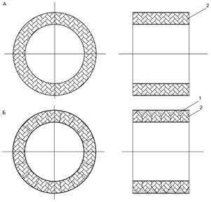
Fig. 1 - Construction of rotary kiln lining, 1 - fiber structure, 2 – chamotte
The greatest decreasing of heat loss in the furnace environment and weight lining can be achieved through the installation of shaped refractory materials in high-temperature zone of the furnace, which also provides a large heat transfer with material and decreased thermal mass unit [8]. On the Fig. 1 is shown the construction of the thermal insulation, which is based on the firebrick cabinet with legs formed by cells. Under mechanical and thermal loads that occur during operation, the reduced form provides better preserve mechanical stability of refractory bricks and ensure high thermal efficiency.
The aim of the study is to investigate the options for mounting a shaped refractory linings of various configurations, taking into account both thermal efficiency and structural reliability.
The task of the research is the need to obtain the temperature fields and the development of methods of calculation of temperature fields in the body of the refractory. Data on the temperature field in the masonry stove obtained based on mathematical modeling.
To estimate the thermal fields apply the heat equation (1), in a Cartesian coordinate system.
The initial and boundary conditions for the solution of differential equations takes the high-temperature sintering zone of a rotary kiln. [7,8]
The temperature on the inner surface and the rotary kiln tin = 1873 ºК;
the temperature of the environment tenv = 300 К;
thermal conductivity of refractory fireclay is defined as a function of temperature![]() , t – temperature chamotte refractory material, C
, t – temperature chamotte refractory material, C
thermal conductivity of basalt fiber λbas = 0,06 W/(m ∙ ºК);
density of chamotte ρcham = 1800 kg/m3;
density of basalt fiber ρbas = 200 kg/m3;
convective heat transfer coefficient on the outside of the oven α = 30 Вт/(m2 ∙ ºК) [4,8].
The thickness of the lining to take in accordance with the technological requirements of the rotary kiln [4,5,8].
The solution of differential equations are derived by means of a software package ANSIS 14.0 using the finite element method. As a generator of a finite element mesh used package ICEM CFD 14.0. The resulting finite element mesh are shown in Figures 2 and 3.
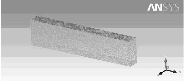
Fig. 2 - The finite element mesh for the standard construction lining
The number of items 46672, number of nodes 8153, the average size of a finite element 0.02 m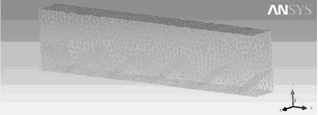
Fig. 3 - The finite element mesh lining for new construction
The number of items 47693, number of nodes 8124, the average size of a finite element 0.02 m
On the basis of (1) The temperature field of fireclay refractory lining in Figure 4, and the new design lining in Figure 5
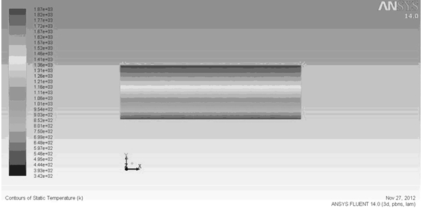
Fig. 4 - The temperature field in the standard construction of the kiln’s lining
q = 6427 W/m2 - the heat flux through the external surface Text= 514 ºK - the average temperature on the external surface of the kiln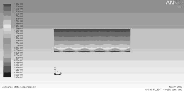
Fig. 5. The temperature field in the new proposed construction of the rotary kiln’s lining
q = 2671 W/m2 - the heat flux through the external surfaceText= 389 ºK - the average temperature on the external surface of the kiln
Based on the thermogram can draw conclusions about the new construction of the lining:
1) By creating a layer of basalt fibers on the outer edge of fireclay lining result in lower temperature of 125 ºK.
2) The decrease of the heat flux through the new design lining is 2.4 times less than the standard lining.
3) Application of the new liner design reduces fuel consumption, as reduce heat loss to the environment. This helps reduce harmful emissions.
4) Application of the new design will reduce the share of the lining of heat loss proportional to the decrease of the heat flux.
References
- Ходоров Е.А. Печи цементной промышленности. Ленинград, , 1968, 432 c.
- Чудновский A.Ф., Теплофизические характеристики дисперсных материалов./ Физматгиз, М.,1962, с.323.
- Кривандин В.А. Теплотехника металлургического производства. Т. 1 / А.В. Кривандин, В.А. Арутюнов, В.В. Белоусов. − М.: Изд. МИСиС, 2002. – 608 с.
- Линер А. Еремин Н.,Линер Ю.,Певзнер И. Производство глинозема// M.,Металлургия, 1978, 344с.
- Steffen W. Hydrogen energy from coupled waste gasification and cement production – a thermochemical concept study / W. Steffen, S. Hamel and W. Krumm // International Journal of Hydrogen Energy. – 2006. – Vol. 31. – Issue 12. – P. 1674-1689
- U. Kaantee, R. Zevenhoven, R. Backman, M. Hupa. Cement manufacturing using alternative fuels and the advantages of process modeling// Fuel Processing Technology №85. 2004 г. P. 293-301
- Кривандин В.А., Филимонов Ю.П., Теория, конструкции и расчеты металлургических печей. / M.: Металлургия, 479 с.
- Кутутеладзе С.С. Основы теории теплопередачи, М., Атомиздат, 1990, 416 с.