ПОСТРОЕНИЕ FE СЕТИ ПОСРЕДСТВОМ ТРЕУГОЛЬНЫХ ПОДРАЗБИЕНИЙ
Берзин Д.В.
Кандидат физико-математических наук, доцент, Финансовый университет при Правительстве Российской Федерации, Москва
ПОСТРОЕНИЕ FE СЕТИ ПОСРЕДСТВОМ ТРЕУГОЛЬНЫХ ПОДРАЗБИЕНИЙ
Аннотация
В работе предложен новый алгоритм для построения треугольной сети для поверхности NURBS, заданной посредством контрольных точек. При этом используются две техники подразбиений – Modified Butterfly и Loop.
Ключевые слова: NURBS, контрольные точки, система автоматизированного проектирования, треугольная сеть, подразбиения.
Berzin D.V.
PhD, Associate Professor, Financial University under the Government of the Russian Federation, Moscow
FINITE ELEMENT MESH AUTOMATIC GENERATION USING TRIANGULAR SUBDIVISION SCHEMES
Abstract
We suggest here a new algorithm for triangular finite element mesh generation for NURBS surface represented as a set of control points. We use a modern approach – subdivision techniques, which has many advantages. Two different subdivision schemes are presented here: Modified Butterfly and Loop ones.
Keywords: NURBS, control points, CAD system, FE mesh, subdivision.
- The problem to solve
Suppose we are given a 2-dimensional surface S, defined by means of control points, for example, by data stored in IGES file type 126 [1]. Thus, we have a set of control points ![]() , weights
, weights ![]() , knot sequence
, knot sequence ![]() , where i= -1, … , L+1; j=-1, … , M+1; n=0, …, L; k=0, … , M. And the corresponding NURBS surface has the following parametric form:
, where i= -1, … , L+1; j=-1, … , M+1; n=0, …, L; k=0, … , M. And the corresponding NURBS surface has the following parametric form:
where ![]() are B-spline functions ([2], Ch.10,17).
are B-spline functions ([2], Ch.10,17).
Triangular patches in CAD system development have certain advantages over quadrilateral ones ([2], Ch.24). For example, they do not suffer from some kinds of degeneracies and are thus better suited to describe complex geometries than are rectangular patches.
Our task is to construct a triangular finite element mesh satisfying the conditions ([3], [4], [5]):
Triangles should satisfy an aspect ratio, i.e. they must be close to regular triangles. Nodes of triangles must lie exactly on the given surface S. The distance d between triangle and surface should be less than number ε, chosen by a user. User should be able to change the mesh adaptively (e.g., density of the mesh in some areas, the number ε, and so on).
- Solution of the problem
Without loss of generality, consider a bicubic B-spline surface S.
Step 1. Bringing a bicubic B-spline surface into a piecewise bicubic Bezier form. This is a standard CAGD procedure ([2], Ch.17), and can be realized by a subroutine, say, “Bezier”. Suppose, now we are given a rectangular net of points ![]() . All of them lie on S . Consider a planar rectangular domain R, spanned on points
. All of them lie on S . Consider a planar rectangular domain R, spanned on points ![]() , that there is a homeomorphism
, that there is a homeomorphism
![]()
Remark. In general case there is a polyhedron K instead of rectangle ![]() ([5], Ch.3).
([5], Ch.3).
Step 2. To construct an initial mesh, we pick out points from the set ![]() . We want the initial mesh to be close to the aspect ratio demand. The subroutine, say, “Initial” uses diagonal transpose technique (e.g., see [4]): it starts from the rectangle
. We want the initial mesh to be close to the aspect ratio demand. The subroutine, say, “Initial” uses diagonal transpose technique (e.g., see [4]): it starts from the rectangle ![]() , compares
, compares ![]() , and chooses the shortest diagonal to divide a quadrilateral into 2 triangles. My colleague Nikita Kojekine (see also [8] and [9]) wrote a computer program in C++ to get the results. The program divides each quadrilateral in the same way.
, and chooses the shortest diagonal to divide a quadrilateral into 2 triangles. My colleague Nikita Kojekine (see also [8] and [9]) wrote a computer program in C++ to get the results. The program divides each quadrilateral in the same way.
Subdivision process
Step 3a. For a subdivision process, we suggest an interpolating Modified Butterfly scheme ([6], Ch.4). We can suppose here that, loosely speaking, the subdivision surfaces ![]() approach to a given surface S. Here
approach to a given surface S. Here ![]() , and f (R) is the subdivision surface. After k-th step of subdivision, we obtain a triangular net
, and f (R) is the subdivision surface. After k-th step of subdivision, we obtain a triangular net ![]() , and a corresponding mesh
, and a corresponding mesh ![]() , where
, where
![]()
A user can interactively choose a level of subdivision in different domains. Let the subroutine be called “Subdivision”.
Step 3b. Instead of Modified Butterfly scheme, sometimes it is advantageous to use other triangular schemes. One of most popular of them is (approximating) Loop scheme ([6], Ch.4). The explanation and results for the step 3 follows:
Program “Subdivision”. The program “subdivision surfaces” was created to demonstrate two different triangular subdivision schemes. One is interpolating Modified-Butterfly scheme, second is Loop scheme. The program was written in Microsoft Visual C++ using MFC (Microsoft Foundation Classes) technology, OpenGL and VTK (free-source visualization toolkit) by my colleague Nikita Kojekine. Program reads initial mesh files first. The very simple format was developed for them.
For example:
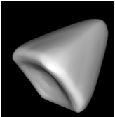
Fig. 1 - Tetrahedron interpolated using Modified Butterfly Scheme, after 6 steps subdivisions
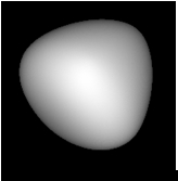
Fig. 2 - Same tetrahedron approximated using Loop scheme, after 6 steps of subdivision
The program is provided with more complex examples of meshes. For example, the ‘rose’ initial mesh and after subdivision: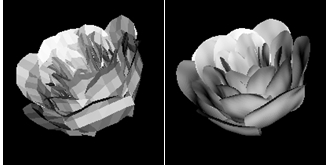
Fig. 3 - Rose. Initial mesh on the left, and approximated image to the right. 3 steps of subdivision using Loop scheme
Another addition to "subdivision" program can be used to demonstrate the interpolation of colors using Modified Butterfly scheme too. Let us look at the same example with tetrahedron:
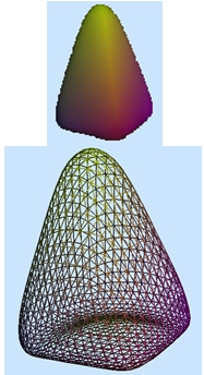
Fig. 4 - Tetrahedron after 5 subdivisions using Modified Butterfly subdivision scheme
Step 4. After k-th level of subdivision we project (by a subroutine, say, “Projection”) a mesh ![]() onto the surface S. Let
onto the surface S. Let ![]() , where P is a projection,
, where P is a projection, ![]() .
.
Step 5. Now one should verify a condition 3). We suggest here to use a distance d1 between a barycenter of corresponding triangle and S (instead of d), and verify a condition ![]() . Let the subroutine be called “Distance”. For the mesh to be conforming, we can use a method from [7] for dividing big triangles into several smaller ones.
. Let the subroutine be called “Distance”. For the mesh to be conforming, we can use a method from [7] for dividing big triangles into several smaller ones.
References
- “Fuji technical research” company. Private communications, Tokyo, 2000.
- Gerald Farin “Curves and surfaces for CAGD”. Academic press, 1993.
- Ichiro Hagiwara. Private communications, Tokyo Institute of Technology, 2000.
- Ho-Le K. “Finite element mesh generation methods: review and classification”. Computer-Aided Design, 20:27-38, 1988
- K.-J. Bathe “Finite Element Procedures”. Prentice-Hall, 1996
- “Subdivision for Modeling and Animation”. SIGGRAPH 99 Course Notes.
- Rivara M.C. “Algorithms for refining triangular grids suitable for adaptive and multi-grid techniques”. Int. J. Numer. Meth. Eng. Vol 20 (1984) pp. 745-756.
- Dmitry Berzin "Finite element mesh generation using subdivision technique" // Research Journal of International Studies, №8 (27) 2014, p. 6
- Dmitry Berzin "Finite element automatic mesh generation using Modified Butterfly subdivision scheme" // Research Journal of International Studies, №8 (27) 2014, p. 8