ОБРАЗОВАНИЕ МИКРОРЕЛЬЕФА ПОВЕРХНОСТИ ПРИ ТОЧЕНИИ КОНУСНЫХ ДЕТАЛЕЙ
Каймин В.Г.1, Сабиров Ф.С.2
1Аспирант, 2Доктор технических наук, Московский государственный технологический университет «СТАНКИН»
ОБРАЗОВАНИЕ МИКРОРЕЛЬЕФА ПОВЕРХНОСТИ ПРИ ТОЧЕНИИ КОНУСНЫХ ДЕТАЛЕЙ
Аннотация
Ранее в работах [1, 2] освещен вопрос влияния вибраций металлорежущего станка на качество образования конических поверхностей (шероховатость). В данной статье рассмотрим образование микрорельефа конической поверхности при точении на станке.
Ключевые слова: вибродиагностика, станки, вибрации
Kaymin V.G.1, Sabirov F.C.2
1Postgraduate student, 2PhD in Engineering, Stankin Moscow State Technological University (Stankin MSTU)
THE FORMATION OF SURFACE MICRORELIEF WHEN GRINDING CONICAL PARTS
Abstract
Earlier works [1, 2] cover the issue of the influence of vibration of the metal-cutting machine on the quality of formed conical surfaces (roughness). This article covers the formation of microrelief of conical surface when grinding on the metal-cutting machine.
Keywords: vibrodiagnostics, machine tools, vibrations.
A line in space can be considered as a trajectory of the point's movement, in this case it is set by vector equation ![]() or parametric equations of the projections of the vector:
or parametric equations of the projections of the vector: ![]() . Because the M point moves along a generatrix of the circular cone, and the cone itself rotates uniformly around the axis, the point moves along a helical line, let's proceed to the parametric equation of the helix:
. Because the M point moves along a generatrix of the circular cone, and the cone itself rotates uniformly around the axis, the point moves along a helical line, let's proceed to the parametric equation of the helix:
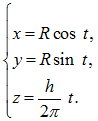
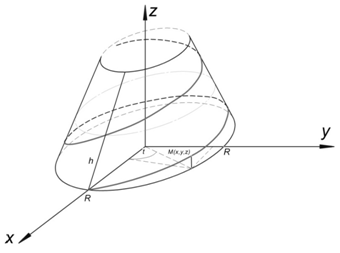
Fig. 1
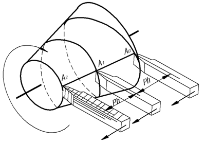
Fig. 2
If the cutter is set to evenly forward motion, and the cone is set to evenly rotational motion, it will result in the end of the cutter, i.e. point A, leaving a line called conical helix on the surface of the cone, Fig.2. In the example given, A0 point after one turn will move from position A0 to the position A1, forming a first wreath, and after the second turn will move from position A1 to position A2, forming a second wreath. The distance parallel to the axis of the cone from point A0 to point A1, is the tour of a conical helix. Projection around the axis of the cone will be a spiral of Archimedes, and the front one – will be sine wave with a decreasing altitude of wreaths (“decaying curve”). Parametric equations of the line will be: ![]() provided that the point moves at a constant speed, and the cone rotates evenly around its axis at a constant angular velocity. From a technical point of view, a helix is a trace of movement of the cutting tool along the workpiece, however, these dependencies are only suitable for the case when the instrument has an ideal profile, and the movement is of the linear dependence.
provided that the point moves at a constant speed, and the cone rotates evenly around its axis at a constant angular velocity. From a technical point of view, a helix is a trace of movement of the cutting tool along the workpiece, however, these dependencies are only suitable for the case when the instrument has an ideal profile, and the movement is of the linear dependence.
Let's review the model of the formation of the microrelief surface when grinding. We shall introduce the relative coordinate system ![]() associated with the cutting tool. Let the cutting edge be a flat curve. In the cutting plane C (front subspace of the cutting tool) we shall place axes
associated with the cutting tool. Let the cutting edge be a flat curve. In the cutting plane C (front subspace of the cutting tool) we shall place axes ![]() and
and ![]() so that
so that ![]() axis is parallel to the nominal surface (i.e. to the ХОY plane of absolute coordinate system), and
axis is parallel to the nominal surface (i.e. to the ХОY plane of absolute coordinate system), and ![]() axis is perpendicular to
axis is perpendicular to ![]() axis.
axis. ![]() axis shall be positioned normal to the plane of the cutting edge (Fig. 3). [3]
axis shall be positioned normal to the plane of the cutting edge (Fig. 3). [3]
Fig. 3 - Relative coordinate system
The origin of the relative coordinate system is compatible with the apex of the cutting edge. The position of the relative coordinate system is defined by three coordinates ![]() of the origin of coordinates and rotation angles µ and ʋ of the plane of the cutting edge in relation to the absolute coordinate system. µ angle is equal to the angle between the trace of Pc plane of the cutting edge on ХОY plane and
of the origin of coordinates and rotation angles µ and ʋ of the plane of the cutting edge in relation to the absolute coordinate system. µ angle is equal to the angle between the trace of Pc plane of the cutting edge on ХОY plane and ![]() axis.
axis.
ʋ angle is equal to the angle between С plane of the cutting edge and ХОY plane. Let's define the equation of the cutting edge in the relative coordinate system in the form: ![]()
The equation of the cutting edge in the absolute coordinate system has the form:
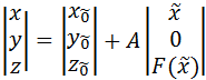 ,
,
where the first vector represents the coordinates of the vertex of the cutting edge, and A transformation matrix has the form
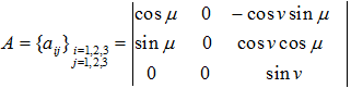
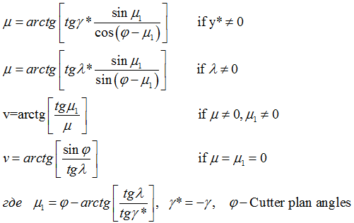
As the cutting tool is fixed, and the part performs rotational and rectilinear movements touching the cutting tool (i.e., µ=const and ʋ =const), the angular position of the plane of the cutting edge in the absolute coordinate system remains unchanged. Angles µ and Ʋ that characterize the position of the plane of the cutting edge in the absolute coordinate system of the part, are connected with the cutting tool angles γ (front angle) and λ (the angle of inclination of the cutting edge) under the following relations:
The equation of the guide line is obtained from the equation of the instantaneous normal deviations:
![]() [4]
[4]
(where К is the coefficient of relative scattering of the output parameter,
Кi is the coefficient of relative scattering of elementary errors, which characterizes the ratio of the error scattering field in the normal law of distribution to the actual scattering field) and equations of the scanning movement [3]:
![]() ,
,
where ![]() is the entry angle of the cutting edge in the treated workpiece surface,
is the entry angle of the cutting edge in the treated workpiece surface,
![]() is the exit angle of the edge from the treated workpiece surface,
is the exit angle of the edge from the treated workpiece surface,
INT is a sign of extracting the integer part of the expression,
Ω is the angular velocity of the main movement.
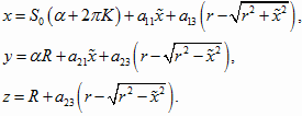
The guide line equation takes the form:
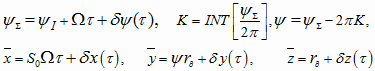
where ![]() is the angle of rotation of the workpiece at the moment of
is the angle of rotation of the workpiece at the moment of ![]()
S0 is the reverse flow
![]() is the difference between the radii of the bases of the truncated cone part.
is the difference between the radii of the bases of the truncated cone part.
The equation of the real surface can be written as:
Having the real surface equation, we shall define roughness parameters:
![]() Rz is the height of the roughness at ten points;
Rz is the height of the roughness at ten points;
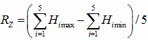
where Himax is the height of the i-th largest profile peak
Himin is the depth of the i-th largest profile valley
L is the basic length
n is the number of selected points of the profile on the basic length
Conclusions:
- The idea of the formation of microrelief surface when grinding has been formulated.
- The mathematical model of the formation of real surface when processing by the cutting tool on the cone surface has been developed.
- The formula for calculating the surface roughness for the real surface has been derived.
References
- V.G. Kaimin, F. S. Sabirov. The influence of dynamic characteristics of the machine on the quality of the treated surface // International Research Journal , issue: 2-1 (21) 2014 (pages 91-92)
- F.S. Sabirov, V.G. Kaimin, A.N. Petrov. The influence of vibrations of the machine on the quality of the treated surface // Modern trends in metalworking technologies and structures of metalworking machines and components. Interuniversity Scientific Collection. Ufa State Aviation Technical University, 2014, pages 117-120
- F. S. Sabirov. Productivity and accuracy of the workspace of machine tools. / Moscow. FGBOU VPO MGTU "STANKIN", 2012, page 175
- Guide of mechanical engineering technologist. Edited by A.G. Kosilova and R. K. Meshcheryakov. Volumes 1 and 2. Moscow. Mechanical Engineering, 1985.