ПРОГРАММНО-АППАРАТНЫЙ КОМПЛЕКС ДЛЯ ЗОНДИРОВАНИЯ МЕТЕОРНЫХ СЛЕДОВ
Лебедева А.А.
ORCID: 0000-0003-1014-1109, Студентка 1-го курса магистратуры, Поволжский государственный технологический университет
ПРОГРАММНО-АППАРАТНЫЙ КОМПЛЕКС ДЛЯ ЗОНДИРОВАНИЯ МЕТЕОРНЫХ СЛЕДОВ
Аннотация
В статье рассмотрены основные физические принципы метеорной радиосвязи. Предложена структурная схема программно-аппаратного комплекса для зондирования метеорных следов. В основу комплекса заложены принципы программно-определяемой радиосистемы. В работе приводится функциональная схема цифрового гетеродина, а так же описание программного обеспечения с примером принимаемых данных. Данный комплекс позволяет устранить ряд недостатков метеорной радиосвязи, а также повысить ее дальность и защищенность.
Ключевые слова: метеорная радиосвязь, программно-определяемая радиосистема.Lebedeva A. A.
1ORCID: 0000-0003-1014-1109, A candidate for a Master's degree, Volga State University of Technology
SOFTWARE AND HARDWARE SYSTEMS FOR SOUNDING METEOR TRAILS
Abstract
The article describes the basic physical principles of meteor radio. A block diagram of hardware and software for sensing meteor trails. The principles of software-defined radio system lies at the heart of the complex. The paper presents a functional diagram of a digital oscillator, as well as software description with an example of the received data. This complex allows eliminating a number of shortcomings meteor radio, as well as increasing its range and security.
Keywords: meteor radio, software-defined radio.The Earth is constantly bombarded by particles of interplanetary material from outer space. Upon entering the earth's atmosphere, along the route of the decaying particle, rapidly disappearing ionized tracks occur. The trace length can be up to 15 km with a width of about 20 meters, such flow can exist from 200 ms to 1 s. These tracks are different from the normal linear electron density and effectively reflect radio signals in the range of 40-100 MHz. Due to this, the radio signal sent by the transmitter into the atmosphere, is reflected off the meteor channel and transmitted to the Earth.
Since the development of the meteor trails is sporadic, the meteor radio systems allow, in the UHF band at long distances with small capacity and simple antennas, to ensure secrecy and immunity, low exposure to natural and artificial ionospheric disturbances and, therefore, the reliability of communication.
The radiophysical fundamentals of meteor communication are as follows. The meteor trail is a natural passive repeater. To get the directions to a mirror image, the meteor trail should take place on a tangent to one of the family of ellipsoids of rotation with focus point transmission and reception point. The meteor traces satisfying the specular reflection condition, are potentially useful for communication. The presence of geometric and energy constraints leads to the fact that not all the meteor traces occurring in the meteor zone (85 - 120 km) of the ionosphere can be used for communication, and reflected radio waves in the meteoric channel will only be accepted from the very limited areas of the meteor zone.
The optimal frequencies are in the range of 35-60 MHz. Although they are not rigid boundaries, but the frequencies outside this range have limited use. The lower limit is set to reduce the effects of atmospheric noise and space, the physical size of antennas and signal attenuation due to so-called D-layer of the ionosphere. At the frequencies above 60 MHz, the phase dispersion of multipath limits the useful duration of the meteor trail.
An important prerequisite for the meteor communication technology is the choice of frequencies. Only at the bottom of the VHF the right combination of receiver sensitivity and reflecting meteor trail ability can be found to create a viable system.
The meteor communication systems are highly effective when used in the radio band. Radio frequency is not enough, and the increasing need for information requires the economical use of the radio spectrum. Since the vast territories of different service users "served" by different meteors, the interference between users virtually eliminated, even if the same frequency is used in a very large area. Thus, all Europe may be serviced by one or two channels, depending on the configuration of the communication network.
If the communication system is formed as a star with a central base station and a certain number of remote stations, the limited communication capacity balance is disturbed by remote terminal stations. In case a mobile terminal is applied, the use of the omni-directional antenna will also affect the balance due. To restore the balance in the communication channel, the transmit power gain of the receiving base station antennas must be increased. To obtain an acceptable energy potential power line communication, the terminal should be around 100 watts.
Larger systems can be built using multiple base stations connected directly. Depending on the layout of the network, it is possible that the base station A located in the area of the base station B and vice versa. When using a single frequency channel for communication across the network it is likely that base stations will interfere the connection with the remote communication stations. Due to the high transmitter power and high gain of the receiving antenna, the connection between two base stations will have a much lower latency, which increases the level of interference. Defining one frequency channel for transmitting and receiving a single frequency channel to the base station, the interference between two base stations may be excluded, and the meteor communication channel can be used more efficiently. The two channels will be used by remote stations in the reverse order.
The GMSK-modulation is usually used to minimize the interference of adjacent channels (Gaussian Minimum Shift Keying modulation- Gaussian minimum shift modulation). The communication protocols are designed to provide 90% of the coefficient of traffic load.
The meteor trail coverage area may be defined as a ground region in which a specific time and a specific location of the transmitter, the power of the received signal exceeds a threshold. Such zone can be more accurately called an instantaneous service area, because its size and location is changed during the pulse. As it might be expected, the size of the zone increases and then decreases, and the location is changed, as a result of displacement of the meteor trail because of the winds in the upper atmosphere.
The size of the service area is an indicator of the degree of connection security. A small service area provides a low detection probability. The most important factor affecting the size of the service area is the location of the track relative to the transmitter and receiver. The meteor traces extending close to the transmitter to form a large service area. As a consequence, the service area for the two transmissions back and forth may be of different sizes.
The block diagram of the transmitter (Figure 1) consists of a GPS / Glonass module GEOS-3 device coordinates position (needed to calculate the distance between the transmitter and receiver and a delay in the signal distribution) and synchronization of time scales. The structure of the block diagram also includes a direct digital synthesizer (DDS) for frequency 1508PL9T necessary for communication. To increase the power of the radio signal to the required level, the power amplifier (PA) is applied. The main requirements to the power amplifier is the low distortion of the transmitted signal and high efficiency.
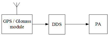
Fig. 1- The block diagram of the transmitter
The receiving part (Figure 2) of the hardware-software complex includes an input filter (1), an analog-to-digital converter (ADC) (2), a digital heterodyne (3), computers (4), a digital computer synthesizer (DDS) (5), and a synchronometer (GPS module / Glonass) (6).
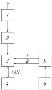
Fig. 2 - The block diagram of the receiving part
At the core of the receiving part is a digital oscillator. Initial signal processing is performed in the digital local heterodyne in the future data received through the PCI interface to a personal computer (PC) with special software installed. Functional diagram of the digital heterodyne is shown in Figure 3.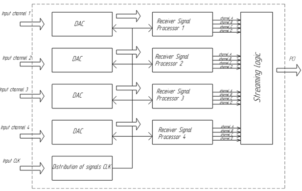
Fig. 3- Functional diagram of the digital heterodyne
The software is based on modified free program Spectrum Lab with special script and upgraded software SRM-3000 application.
Working window of the program's SRM-3000 application is shown in Figure 4, examples of the received data are presented in Figure 5.
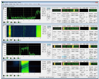
Fig. 4 - Operating window SRM-3000 application
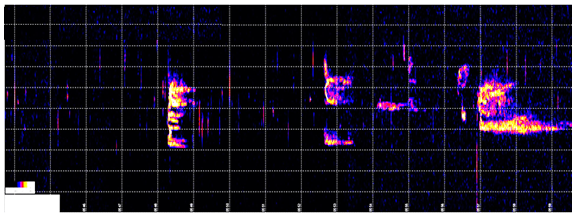
Fig. 5 – Example of received data
References
- Ryabov I.V., Tolmachev S.V. SDR-receiver for radio meteor // In: Proceedings of the 15-th International Conference “Digital Signal Processing and its Applications” (DSPA'2013), Vol. 2. Moscow, Russia, 2013.
- Ryabov I.V., Tolmachev S.V., Chernov D.A. SDR receiver on FPGA for the study of radar reflections from auroras // In: Proceedings of the 16-th International Conference “Digital Signal Processing and its Applications” (DSPA'2014), Vol. 2. Moscow, Russia, 2014.
- Ryabov I.V., Tolmachev S.V., Chernov D.A. Programming FPGA family Xilinx company ZYNQ using MatLab and Simulink to study meteor radio // In: Proceedings of the 17-th International Conference “Digital Signal Processing and its Applications” (DSPA'2015), Vol. 2. Moscow, Russia, 2015.
- Ryabov I.V., Tolmachev S.V., Lebedeva A.A. Hardware-software complex for detection of meteor trails // In: Proceedings of the 18-th International Conference “Digital Signal Processing and its Applications” (DSPA'2016), Vol. 2. Moscow, Russia, 2016, p. 603-608.
- Ryabov I.V., Tolmachev S.V., Lebedeva A.A. Automated hardware-software system for remote detection of meteor trails // In: Proceedings of the XXII-th International Conference “Radiolocation, Navigation, Communication” (RLNC '2016). Voronezh, Russia, 2016.
- Hinrichs, J., Dyrud, L. P., and Urbina, J. Diurnal variation of non-specular meteor trails // Annales Geophysical. 2009. Vol. 27(5). P. 1961-1967.