АНАЛИТИЧЕСКИЙ ОБЗОР ПОДХОДОВ К СТРУКТУРНО-ИМИТАЦИОННОМУ МОДЕЛИРОВАНИЮ БЕТОНА
Курбатов Ю.Е.
ORCID: 0000-0001-6497-2771, Аспирант, Пермский национальный исследовательский политехнический университет
АНАЛИТИЧЕСКИЙ ОБЗОР ПОДХОДОВ К СТРУКТУРНО-ИМИТАЦИОННОМУ МОДЕЛИРОВАНИЮ БЕТОНА
Аннотация
Описание совместной работы разнородных по свойствам фаз в рамках структурно-имитационного моделирования композитов является весьма актуальной задачей в строительной сфере. В данной работе автором выполнен аналитический обзор существующих подходов к моделированию такой сложной композиционной структуры как бетон. Продемонстрированы этапы тщательной проработки процесса моделирования матрицы, заполнителя и пор, включающие в себя создание их геометрии и ориентации элементов в пространстве; назначение эффективных свойств; закрепление созданной модели и её загружение. Представлены различные варианты геометрической формы заполнителя, пор, указаны диапазоны варьирования их характерными размерами и ориентацией в пространстве цементной матрицы. Данная статья является основой для проведения вычислительного эксперимента, включающего в себя все вышеуказанные этапы для получения новых данных о процессе постепенного накопления повреждений в структуре бетона при воздействии статической нагрузки.
Ключевые слова: начальные дефекты структуры, седиментационные явления, структурно-имитационное моделирование, нормальный закон распределения, концентрация включений.
Kurbatov Y.E.
ORCID: 0000-0001-6497-2771, Postgraduate student, Perm National Research Polytechnic University, Perm, Russia
ANALYTICAL REVIEW OF APPROACHES TO THE STRUCTURAL-SIMULATION MODELING OF CONCRETE
Abstract
The description of the diverse properties phases’ joint work in the framework of structural-simulation modeling of composites is one of the most urgent tasks in the construction industry. In this paper the author carries out an analytical review of existing approaches to modeling of the complex composite structures such as concrete. The paper shows careful consideration stages of the modeling process of the matrix, filler and pores. These stages include the creation of the geometry and orientation of elements in space; assigning effective properties; binding the created model and it’s loading. Presents various ways of forming the geometrical shape of the filler and pores. Then, shows the range of variation of their characteristic size and their orientation in the space of the cement matrix. This article can serve as a basis for the computational experiment, including all the above phases and provides new information about the process of gradual damage accumulation in the structure of concrete under static loads.
Keywords: initial structure defects, sedimentation phenomena, structural-simulation modeling, normal distribution law, concentration of inclusions.
Improving the efficiency of construction, reducing the cost and complexity of technological processes and a number of other relevant tasks in the construction industry are inextricably linked with using and development of new progressive building materials based on concrete [1]. The structure of such materials is a highly concentrated particulate system, which have the inter-particle contact interactions, including those between the cement stone and filler. It is evident the need of performance the physical-mechanical properties of the composites in the form of mathematical relationships between their internal structure and external influences in the given conditions. These relationships will allow to identify the factors that ensure the creation of efficient structures of materials, as well as to evaluate the durability and reliability of designs without lengthy and expensive field experiments. The description of such complicated-structured systems should provide a reflection of the distribution in volume, the relative orientation of the pair-forming elements, and the consideration of their joint work at various levels. This approach involves the use of the structural-simulation modeling technology. Modeling of various real situations on simulation models allows to solve the problem of comparison the different variants of the system structure and to determine the degree of influence the system parameters changes and initial conditions on the efficiency indicator of the simulated system.
Description of the joint work the phases with heterogeneous properties in the framework of the structural-simulation modeling can be realize in the course of carrying out the computational experiment using a number of numerical methods, the most developed of which is the finite element method. The computational experiment allows to study the relationship between any materials structure and its properties, with reducing the duration of studies. In addition, the computational experiment allows to obtain the data difficult to achieve in the field experiment [2].
In the paper [3] proposed the simulation model of the concrete structure at the macro level in the form of a two-component system consisting of matrix – cement-sand stone, and inclusions of filler grains, in the form of convex polygons. The contact area with properties different from the matrix and filler properties provided on their border. Initial structure defects – pores of different shapes and sizes, – randomly located in the material volume (the matrix). Moreover, the samples of concrete and its components are modeled at the level of the macrostructure as plates, the width and the height of which are equal to the standard dimensions of the samples.
According to the authors, such structural simulation model has geometric and physical parameters similar to the parameters of a real sample. The paper proposed two models of the concrete structure − with porous filler (which can have initial defects), and dense filler. These models are shown in figure 1.
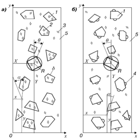
Fig. 1 – The model of concrete structure with porous (a) and dense (b) fillers: 1 – filler; 2 – initial defect of porous filler; 3 – initial defect of cement matrix; 4 – initial defect of contact zone; 5 – matrix
Fillers inclusions are modeled by convex polygons, and have the following geometrical parameters (Fig. 2): conditional radius ![]() , number of vertices
, number of vertices ![]() and their angle
and their angle ![]() regarding the load q, coordinates of the center
regarding the load q, coordinates of the center ![]() and
and ![]() , inclusion concentration
, inclusion concentration ![]() and inclusion shape ratio
and inclusion shape ratio ![]() , physical properties – elastic modulus
, physical properties – elastic modulus ![]() , Poisson's ratio
, Poisson's ratio ![]() .
.
Parameters ![]()
![]() change randomly at predetermined intervals: [
change randomly at predetermined intervals: [ ![]() ], [A; B], [3; 6], [0; 2
], [A; B], [3; 6], [0; 2![]() ] and [
] and [![]() ]. Inclusion concentration
]. Inclusion concentration ![]() is a constant .
is a constant .
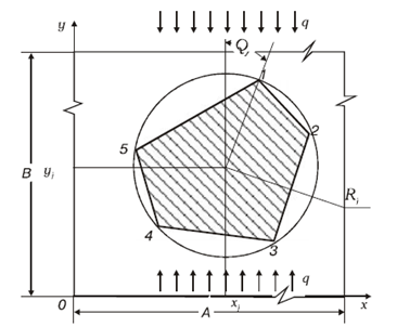
Fig. 2 – Geometric parameters of the filler
The sides of the polygons simulate the surface area of the inclusions (see Fig. 3). Its geometric parameter is the width ![]() which can receive constant or variable value, physical parameters are the critical stress intensity factors under normal gap
which can receive constant or variable value, physical parameters are the critical stress intensity factors under normal gap ![]() and flat shift
and flat shift ![]() .
.
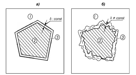
Fig. 3 – The filler inclusion with a constant (a) and a variable (b) width of the contact zone: 1 – matrix; 2 – filler; 3 – contact zone
It should be noted that the geometric characteristics of concrete macrostructure parameters were established by the authors during the field experiment. The shape of coarse filler studied in the concrete polished sections. By visual observation (fig. 4) it was found that nearly all (about 96%) filler contours are convex, and can be described by convex polygons. Statistical analysis of the 460 measurements results showed that 10% of the filler cross-sections can be described as triangles, 50% − quadrangles, 30% − pentagons and 10% − hexagons. The form, size and the fractional composition of the filler hardly affects at this ratio.
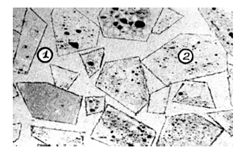
Fig. 4 – Concrete polished sections: 1 – cement-sand stone; 2 – filler
With regard to the initial defects of concrete and its components at the macrostructure level − the pores in the paper [3] modeled as round holes. Two collinear cracks are located on their contour. The pores have the following geometric parameters: pore radius ![]() , the initial crack length
, the initial crack length ![]() , crack orientation
, crack orientation ![]() regarding the load q, coordinates of defects on the plate
regarding the load q, coordinates of defects on the plate ![]() and
and ![]() , number of pores
, number of pores ![]() (fig. 5). Radius
(fig. 5). Radius ![]() in the proposed model changes according given size distribution law. The initial crack length
in the proposed model changes according given size distribution law. The initial crack length ![]() is fixed and reaches
is fixed and reaches ![]() [4]. The defect orientation (relative load q) changes to range from 0 to
[4]. The defect orientation (relative load q) changes to range from 0 to ![]() . Center coordinates are independent random variables. Imperfection inclusions can be ignored in the heavy concrete, because it is represented in the main as violation of crushed granite filler contact with cement-sand stone as a result of sedimentation phenomena.
. Center coordinates are independent random variables. Imperfection inclusions can be ignored in the heavy concrete, because it is represented in the main as violation of crushed granite filler contact with cement-sand stone as a result of sedimentation phenomena.
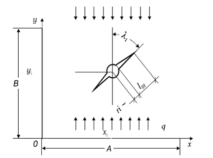
Fig. 5 – The geometrical parameters of the initial defect in concrete macrostructure
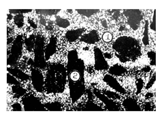
Fig. 6 – The fluorescent inspection of heavy concrete: 1 – cement-sand stone; 2 – filler
Thus, the proposed model of the concrete specimen [3] is regarded as a plate with a unit thickness. According to the authors, under uniaxial compression, this approach does not lead to significant errors in comparison with actual volumetric stress state of the elements.
In addition, the adopted simplification allows to describe the stress state of the concrete structural elements by using known solutions of elasticity theory on the plane, on the basis of which the destruction process can be modeled at the level of concrete macrostructure with the inclusion of the structural elements of the current (matrix, filler, the contact area, initial defects) and previous (field of matrix and inclusions, microcracks) levels. In this case, the destruction of the concrete specimen will correspond to the moment of the unstable structural element formation - the main crack, which comes out on the specimen’s sides, representing a natural boundary for the given material system at the level of the macrostructure.
In [5] and [6] the concrete failure mechanism is studied on the basis of tiered modeling of its structure. A significant effect of porosity on the mechanical properties of the cement stone is noted by authors. They used the finite element method, based on solid modeling and implemented in the ANSYS program, to investigate the effect of pores impact on the stress-strain state of the cement stone. Application of this method along with structural-simulation models allow to simulate the process of cracking in a form, which is close to the physical essence of the real, encompassing not only the pore space, but the solid phase too. This method explicitly takes into account the physical and geometric heterogeneity of composite material [7].
Modern generations of ANSYS allow to create and calculate the three-dimensional models with a wide range of geometries and maximum visualization of the results. It should be noted that the three-dimensional solid modeling allows us to consider the mechanism of concrete cracking from the position of the volume destruction process.
Adopted in [5], [6] design model is a solid isotropic homogeneous cube, which contains the randomly arranged voids (pores) of different sizes. Due to the small pore size, scale modeling was performed with an increase 107 times in the linear dimensions during the preparation of the design scheme.
As a result, the 100x100x100 cube with pores as balls (diameters 15, 20 and 30 mm) was adopted as the research object. Figure 7 shows a specified finite element solid model of cement gel with a porosity of 17.7%.
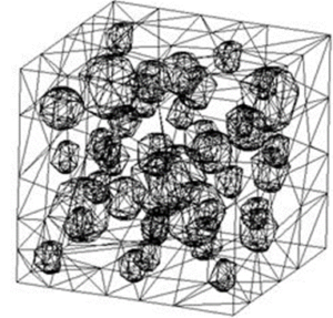
Fig. 7 – The finite element model of cement gel with pores
The geometrical basis of the model created in SolidWorks and then transferred to ANSYS for further calculations. As a finite element in the calculation scheme SOLID92 was adopted, which is a volume tetrahedron with ten nodes. The author's calculations were assumed that the material has a modulus of elasticity equal 70 MPa and has linear properties. Adopted modulus corresponds to the average value for the cement gel, which was determined empirically in the works [8], [9].
Breakdown into finite elements is done automatically using the free way of meshing provided in the ANSYS. Design scheme was established by 83 526 finite elements. The number of nudes was 128 953. To simulate the work material in ”solid”, side and bottom faces of the cube were fixed (prohibited linear movement relative corresponding coordinates). On the top face was applied uniformly distributed compressive load. The increasing of the load applied to the above calculation scheme was carried out in steps. Thus kinetic nature of the destruction simulated. This fact associated with the gradual accumulation of defects in the structure with load growth. The “Birth & Death” function was used to simulate the destruction of the material.
The process of model calculation, proposed in [5], [6], included the following things. Elementwise check on specified criteria was made at the end of each step. Elements deactivated in case of exceeding the criterion, and the calculation was performed again with the preservation of the stress-strain state, calculated in the previous step. Deformation and loads were dropped in the disabled elements. The calculation results are presented in figure 8.
The analysis of figure 8 enables us to conclude that the selected fixing and loading of a solid model does not distort the picture of the stress-strain state: inhomogeneity of stress fields explained the presence of pores and their mutual arrangement. Thus, it can be concluded that there is considerable uneven distribution of stress and strain components in the model volume with the presence of pores.
In [10] A.M. Haritonov develops the approach described above, counting the model of fine-grained concrete structures to track the heterogeneity of stresses distribution in the volume of the material. This heterogeneity was caused by a large difference between the elasticity modulus of cement stone and the elasticity modulus of filler.
The author has created a flat model of the sand-cement composite (50x50 mm), which reflects sand grains (1.0-5.0 mm) and pores (0.8-2.0 mm).
In the simulation of the cracking process in the cement stone author used fracture criterion based on the theory of limit voltages [11]:
![]() (1)
(1)
where ![]() − the ratio of tensile strength to the compressive strength;
− the ratio of tensile strength to the compressive strength; ![]() – main stresses;
– main stresses; ![]() the tensile limit strength.
the tensile limit strength.
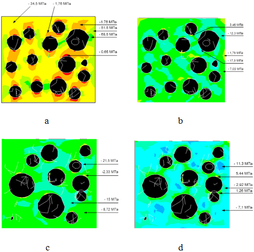
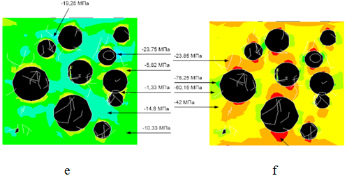
Fig. 8 – The numerical values of the stresses in the plane YOX: a − normal ![]() ; b – normal
; b – normal ![]() ; c – normal
; c – normal ![]() ; d – main
; d – main ![]() ; e – main
; e – main ![]() ; f − main
; f − main ![]()
This criterion implies the destruction of the material in the areas of local extension; it shall be deemed that the criterion ![]() does not apply to explain the reasons for failure under uniaxial compression. However, as the assumptions, author [10] accepted that in the models which take into account the heterogeneity of the material, criterion
does not apply to explain the reasons for failure under uniaxial compression. However, as the assumptions, author [10] accepted that in the models which take into account the heterogeneity of the material, criterion ![]() overcomes these disadvantages. At the same time the destruction of concrete under central compression can be explained by gap on areas which parallel to the direction of the compressive force. In this case, the cause of failure is transverse tensile stresses which arise in the field of macro- and micropores weakening concrete.
overcomes these disadvantages. At the same time the destruction of concrete under central compression can be explained by gap on areas which parallel to the direction of the compressive force. In this case, the cause of failure is transverse tensile stresses which arise in the field of macro- and micropores weakening concrete.
Figure 9 reflects the early stage of crack initiation in the most vulnerable areas under load equal 30% of the critical value. Obviously, the initial cracks occur in the contact area (and thus grains of sand are disabled), as well as on the surfaces of pores.
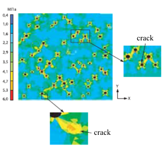
Fig. 9 – The stress ![]() distribution at the level of load equal 30% of the critical
distribution at the level of load equal 30% of the critical
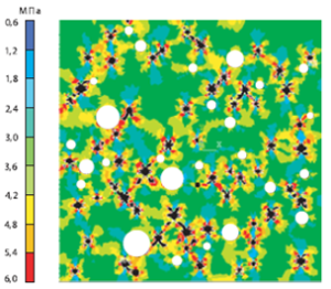
Fig. 10 – The nature of the fine-grained concrete structures destruction at the level of load equal 70% of the critical (white color indicates the filler grains)
Further simulation of the fracture process in the fine-grained concrete structures, described in [10], was carried out with the gradual build-up of external load in compliance with the conditions of short-term exposure for certain levels of loading. Figure 10 shows the nature of the destruction of the structure under a load equal 70% of the critical failure load. At the level of the uniaxial compressive load ![]() , as shown in Fig. 10, there is a tendency of close connection in microcracks, as well as there is a local destruction of the contact zone. However, the output of cracks on the sample surface is not observed. A further increase of the load accompanied by growing degradation of concrete with the formation of backbone cracks emerging on the surface of the sample under the destructive load level. According to the author, the resulting picture of the emergence and development of cracks corresponds to existing ideas about the process of destruction in the cement compositions. This fact allows us to conclude that suggested modeling method of the concrete destruction under uniaxial compression is suitable for theoretical evaluation of the concrete strength.
, as shown in Fig. 10, there is a tendency of close connection in microcracks, as well as there is a local destruction of the contact zone. However, the output of cracks on the sample surface is not observed. A further increase of the load accompanied by growing degradation of concrete with the formation of backbone cracks emerging on the surface of the sample under the destructive load level. According to the author, the resulting picture of the emergence and development of cracks corresponds to existing ideas about the process of destruction in the cement compositions. This fact allows us to conclude that suggested modeling method of the concrete destruction under uniaxial compression is suitable for theoretical evaluation of the concrete strength.
Thus, the main problems of the structural-simulation modeling of the cement concrete were considered in this work. Also this paper provided and summarized some possible implementations of the structure modeling in specific software systems (SolidWorks, ANSYS), developed by skilled scientists. The main conclusion we can conclude that the problem of structural-simulation modeling of the composite concrete elements is complex and requires a careful study in each stage of creating the cement stone, the filler and the pores.
Список литературы / References
- Рабинович Ф.Н. Композиты на основе дисперсно-армированных бетонов. Вопросы теории и проектирования, технология, конструкции: Монография / Ф.Н. Рабинович. – М.: Издательство АСВ, 2011. – 642 с.
- Чермашенцев В.М. Теоретические аспекты компьютерного моделирования эффективных композиционных материалов / В.М. Чермашенцев // Известия вузов. Строительство. – 2002. – № 3. – С. 33–40.
- Кондращенко В.И. Имитационная модель макроструктуры бетона [Текст] / В.И. Кондращенко, В.Д. Кудрявцева, А.В. Кендюк и др. // Сборник научных трудов "Вестник НТУ "ХПИ". – 2010. – №52. – С. 21–35.
- Зайцев Ю.В. Моделирование деформаций и прочности бетона методами механики разрушения / Ю.В. Зайцев. – М.: Стройиздат, 1982. – 196с.
- Харитонов A.M. Прогнозирование трещиностойкости бетона на основе метода конечных элементов / A.M. Харитонов // Десятые Академические чтения РААСН. – Казань: КГАСУ, 2006. – С. 418–420.
- Харитонов A.M. Исследование роли системы пор в распределении внутренних напряжений в цементном камне / A.M. Харитонов // Ресурсосберегающие технологии в транспортном строительстве и путевом хозяйстве железных дорог. Сб. тр. по материалам науч.-практ. интернет-конференции. – СПб.: ООО «Изд-во «ОМ-Пресс»», 2006. – С. 92–97.
- Харитонов А.М. Исследование свойств цементных систем методом структурно-имитационного моделирования / А.М. Харитонов // Строительные материалы. Наука. – 2008. – № 9. – С. 81–83.
- Тимашев В.В. Влияние физической структуры цементного камня на его прочность/ В.В. Тимашев // Цемент. – 1978. – № 6. – С. 6–8.
- Горшков В.С. Методы физико-химического анализа вяжущих веществ / В.С. Горшков, В.В. Тимашев, В.Г. Савельев. − М.: Высшая школа, 1981. – 334 с.
- Харитонов А.М. Принципы формирования структуры композиционных материалов повышенной трещиностойкости / А.М. Харитонов // Технологии бетонов – 2011. – № 3−4. – С. 24–26.
- Тарасенко И.И. О критериях хрупкой прочности материалов / И.И. Тарасенко // Строительная механика и строительные конструкции. − М.: Стройиздат, 1960. Вып. 26. – С. 18–22.
Список литературы на английском языке / References in English
- Rabinovich F.N. Kompozity na osnove dispersno-armirovannykh betonov. Voprosy teorii i proektirovaniya, tekhnologiya, konstruktsii [Composites based on dispersion-reinforced concrete. Theory and design, technology, construction] / F.N. Rabinovich. – M.: Izdatelstvo ASV, 2011. – 642 p. [in Russian]
- Chermashentsev V.M. Teoreticheskie aspekty komp'yuternogo modelirovaniya effektivnykh kompozitsionnykh materialov [Theoretical aspects of computer modeling for effective composite materials] / V.M. Chermashentsev // Izvestiya vuzov. Stroitelstvo [Proceedings of the universities. Building]. – 2002. – № 3. – P. 33–40. [in Russian]
- Kondrashchenko V.I. Imitatsionnaya model' makrostruktury betona [A simulation model of the macrostructure of concrete] / V.I. Kondrashchenko, V.D. Kudryavtseva, A.V. Kendyuk // Sbornik nauchnykh trudov "Vestnik NTU "KhPI" [Collection of scientific papers "Vestnik NTU" HPI”]. – 2010. – №52. – P. 21–35. [in Russian]
- Zaitsev Y.V. Modelirovanie deformatsii i prochnosti betona metodami mekhaniki razrusheniya [Simulation of deformation and strength of concrete by using methods of fracture mechanics] / Y.V. Zaitsev. – M.: Stroiizdat, 1982. – 196 p. [in Russian]
- Haritonov A.M. Prognozirovanie treshchinostoikosti betona na osnove metoda konechnykh elementov [Prediction of concrete fracture toughness based on the finite element method] / A.M. Haritonov // Desyatye Akademicheskie chteniya RAASN [Tenth Academic reading RAASN]. – Kazan': KGASU, 2006. – P. 418–420. [in Russian]
- Haritonov A.M. Issledovanie roli sistemy por v raspredelenii vnutrennikh napryazhenii v tsementnom kamne [Investigation of the role of pores systems in the distribution of internal stresses in the cement stone] / A.M. Haritonov // Resursosberegayushchie tekhnologii v transportnom stroitel'stve i putevom khozyaistve zheleznykh dorog. Sb. tr. po materialam nauch.-prakt. internet-konferentsii [Resource-saving technologies in the construction of transport and road economy of the railways. Proceedings on the materials of scientific and practical Internet-conference]. – SPb.: OOO «Izd-vo «OM-Press»», 2006. – P. 92–97. [in Russian]
- Haritonov A.M. Issledovanie svoistv tsementnykh sistem metodom strukturno-imitatsionnogo modelirovaniya [The study of the cement systems properties by the method of structural-simulation modeling] / A.M. Haritonov // Stroitel'nye materialy. Nauka [Construction Materials. The science]. – 2008. – № 9. – P. 81–83. [in Russian]
- Timashev V.V. Vliyanie fizicheskoi struktury tsementnogo kamnya na ego prochnost' [The influence of the physical structure of a cement stone in its durability] / V.V. Timashev // Tsement [Cement]. – 1978. – № 6. – P. 6–8. [in Russian]
- Gorshkov V.S., Timashev V.V., Savel'ev V.G. Metody fiziko-khimicheskogo analiza vyazhushchikh veshchestv [Methods of physicochemical analysis of binders] / V.S. Gorshkov. − M.: Vysshaya shkola, 1981. – 334 p. [in Russian]
- Haritonov A.M. Printsipy formirovaniya struktury kompozitsionnykh materialov povyshennoi treshchinostoikosti [Principles of formation the structure of composite materials with increased fracture toughness] / A.M. Haritonov // Tekhnologii betonov [Concrete technologies]. – 2011. – № 3-4. – P. 24–26. [in Russian]
- Tarasenko I.I. O kriteriyakh khrupkoi prochnosti materialov [About the criteria of material brittle strength] / I.I. Tarasenko // Stroitel'naya mekhanika i stroitel'nye konstruktsii [Building mechanics and building construction]. M.: Stroiizdat, 1960. Vyp. 26. – P. 18–22. [in Russian]