АНАЛИЗ СУТОЧНОГО ГРАФИКА ЭЛЕКТРИЧЕСКОЙ НАГРУЗКИ ЖИЛОГО ДОМА. РАСЧЕТ ПОТЕРЬ ЭЛЕКТРОЭНЕРГИИ ДЛЯ ТРАНСФОРМАТОРА И КАБЕЛЬНОЙ ЛИНИИ
Калимуллин А. Т.1, Лесков И. А.2, Темников Е. А.3, Грабовецкая К. А.4
1Аспирант, ассистент кафедры Электроснабжение промышленных предприятий, 2Студент 5 курса, Энергетический факультет, 3Студент 5 курса, Энергетический факультет, Омский Государственный Технический Университет
АНАЛИЗ СУТОЧНОГО ГРАФИКА ЭЛЕКТРИЧЕСКОЙ НАГРУЗКИ ЖИЛОГО ДОМА. РАСЧЕТ ПОТЕРЬ ЭЛЕКТРОЭНЕРГИИ ДЛЯ ТРАНСФОРМАТОРА И КАБЕЛЬНОЙ ЛИНИИ
Аннотация
В статье рассмотрены такие актуальные вопросы, как анализ суточного графика электрической нагрузки, расчет потерь электроэнергии трансформатора и питающей многоквартирный дом кабельной линии и экономическое обоснование замены, в случае необходимости, данного трансформатора и кабельной линии. Ведь неравномерность электропотребления, а так же недогруженность трансформатора приводит к большим потерям холостого хода, что в свою очередь вызывает излишние потери не только в самом трансформаторе, но и во всей системе питания и большие экономические убытки для электроснабжающей компании.
Ключевые слова: суточный график нагрузок, кабельная линия, потери электроэнергии, время окупаемости.Kalimullin A. T.1, Leskov I. A.2, Temnikov E. A.3, Grabovetskaya K. A.4
1Postgraduate student, assistant of the department of power supply for industrial enterprises, 2Student 5th year, the Energy Department, 3Student 5th year, the Energy Department, Omsk State Technical University
ANALYSIS OF THE DAILY SCHEDULE OF ELECTRIC LOAD OF A HOUSE. CALCULATION OF ELECTRIC POWER LOSS FOR TRANSFORMER AND CABLE LINES
Abstract
The article deals with topical issues such as the analysis of the daily schedule of electric load, the calculation of the loss of the transformer and power supply house cabling and economic substantiation of the replacement, if necessary, of the transformer and the cable line. After all, the unevenness of power consumption, as well as the underloaded transformers leads to great losses of idling, which in turn causes excessive losses not only in the transformer, but in the whole power system and large economic losses for the power supply company.
Keywords: daily schedule loads, cable line, the loss of electricity, the payback time.For three-phase electricity meter readings (Table. 1) mounted on the input block of flats, the daily schedule of an electrical load of the building depicted in Figure 1. From the resulting graph shows that power consumption is uneven, consequently, the transformer and the power supply cable line losses occur. The calculation of the loss of data, and economic rationale replacement, if necessary, the transformer and the cable line.
Table 1 – Electricity meter reading
| Time measurement, h | 0 | 4 | 8 | 12 | 16 | 20 | 24 |
| Meter reading, kW∙h | 2210,3 | 2213,7 | 2218,2 | 2227,1 | 2233,8 | 2246,3 | 2255,1 |
Table 2 – Initial data transformer and the cable line
| Transformer ТМ-630/10 | Sном.тр, kV∙A | соsj | ΔРх, kVt | ΔРкз, kVt | Uк, % | Iх, % |
| 630 | 0,9 | 1,56 | 7,6 | 5,5 | 2 | |
| Cable line АВВГ-4х95 | L, m | R0, Om/km | ||||
| 60 | 0,32 | |||||
The daily schedule of an apartment house load is shown in Figure 1, six 4 - hour intervals averaging. The average power at each j-th interval based on the scale factor determined by the formula [1]
![]() (1)
(1)
Daily charts show the change in load during the day. They build on the meter readings of active and reactive power every hour or every half hour (to detect a half-hour peak load).
In the design using typical daily schedules are typical for this type of production, in which the daily maximum load is taken as unity or 100%, and the remaining load expressed as a decimal or a percentage. To build a specific daily schedule is necessary to know the maximum load, and have a typical daily schedule.
For daily schedules of active and reactive loads are characterized by the following values: maximum active (reactive) load per day P'm (Q'm) kW (kvar), the most active load in the most loaded changing Pm kW consumption of active (reactive) energy per day Wcut (Vcut), kWh (kvar-h), consumption of active (reactive) power for the most loaded shift Wcm (Vcm), kWh (kvar-h).
To determine the power consumption accounted transformer universal counter for any amount of time necessary difference in the readings taken at the beginning and end of this period, multiplied by a conversion factor.
Conversion kП factor determined by the formula [2]
![]() (2)
(2)
where KI - transformation ratio of current transformers;
KU - ratio voltage transformer.
According to the requirements of GOST removable shields these counters must be the inscription "current transformer", "voltage transformer", "K ...." next to that subscriber are put ratio and conversion factor.
Conversion factor equal to the counter 40 (including through current transformers with transformation ratio 200/5).
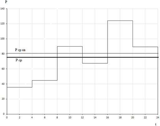
Fig. 1 – The daily schedule of the apartment building load
The electricity consumed by the house for the day, by the difference between the first and the last counter readings of EE given conversion factor (transformation ratio) [1]
![]() (3)
(3)
or directly by summing the power schedule of electric load [1]
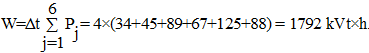 (4)
(4)
We define indicators characterizing uneven electricity. Time use maximum [1]
![]() (5)
(5)
allows you to define the schedule form factor [1]
![]() (8)
(8)
and the duty ratio of the daily schedule [1]
![]() (9)
(9)
The value of the latter can also be determined by using the peak load time [1]
![]() (10)
(10)
Irregularity ratio of electricity [1]
![]() (11)
(11)
These figures reflect a significant ripple and low power consumption density in the apartment building during the day. The calculated energy loss in the transformer brands ТМ-630/10 and CL АВВГ-4х95 are summarized in Table 3.
Table 3 – The calculated value of the transformer and the mains cable line
| Transformer ТМ-630/10 | RMS power load, kVA | 89,5 |
| The load factor of the transformer | 0,142 | |
| The number of hours of use maximum, h | 5247 | |
| The greatest losses time, h | 3696 | |
| The losses of active energy in the transformer during the year, kVt∙h | 14269 | |
| CL АВВГ-4х95 | Total cable resistance, Om | 0,0192 |
| Rated current per hour maximum power grid, А | 136 | |
| Losses of electricity in the year cable, kVt∙h | 3938 |
The calculation and feasibility study of the transformer replacement ТМ-630/10, installed on the substation ТП-1 transformer less power ТМ-160/10.
After analyzing the graph of electrical loads determined that the rms power of the transformer ТМ-630/10/0,4 on ТП-1 is 89,5 kV∙А. Consequently, the load factor of the transformer [3]
![]() (12)
(12)
This shows that the transformer is actually underloaded, leading to large losses of idling.
The loss of electrical energy in the transformer 630 kV∙A comprise
ΔWтр1 = 14269 kVt×h/year,
that in terms of money at the cost of 1 kW∙h of electricity 3.32 RUB (for Omsk at the time of 06.25.16) will be [3]
![]() (13)
(13)
Table 4 – The calculated values for the energy loss in the transformer ТМ-160/10
| Transformer ТМ-160/10 | RMS power load, kVA | 89,5 |
| The load factor of the transformer | 0,56 | |
| The greatest losses time, h | 3696 | |
| The losses of active energy in the transformer during the year, kVt∙h | 8035 |
It is necessary to determine the cost of installation work on the replacement of the transformer. Conventionally, we assume that it is an average of 30% of the cost of the transformer. The cost of the transformer TM-160/10 is 114.45 thousand. rub. Hence installation costs amount to
З1 = 0,3·114,45=34,33 thousand. rub. – the construction costs;
З2 = 114,45 thousand. rub. – transformer cost;
The residual value of the replaced transformer (transformer cost of sales used adjusted for depreciation) of 30 % of the cost of new transformer of the same power.
К=0,3·289,38=86,81 thousand. rub. – liquidation value of the replaced transformer.
Payback time with the liquidation value of the replaced transformer
![]() (15)
(15)
We manufacture replacement АВВГ-4x95 cable on the cable of larger cross section АВВГ-4x120.
Total cable resistance for a given length of 0.0152 ohms.
A loss in the cable for the year amounted to 3113 kW∙h. loss cost
![]() (16)
(16)
![]() (17)
(17)
З1 = 300·60=18 thousand. rub. – installation costs (cost 250-300 rub./m. to Omsk);
З2 = 400·60=24 thousand. rub. – cable costs;
Time payback cable replacement
![]() (18)
(18)
Conclusion.
Payback time of up to 6 years old is considered to be acceptable for the implementation of measures for replacement of equipment [4]. Since the basis of the result of the calculation, the replacement of the transformer TM - 630/10 by the transformer less power, payback time was 3 years, therefore, the calculation is made correctly and the event of replacement of the transformer is acceptable for implementation. In addition, the increase in electricity tariffs to further reduce the payback period over the years.
It should also be noted that the operation of transformers at idle or close to it causes excessive loss not only in the transformer, and power throughout the system because of low power factor at idling transformer. However, the results obtained with respect to the replacement of the cable line is not suitable for implementation of activities, as Payback time was 14 years, which is very much.
References
- Calculation of electrical loads, the choice of the main circuit equipment of objects of power supply systems: Proc. Benefit / V.C. Grunin, V.F. Nebuskin, V.K. Fedorov, A.D. Ernst; Under the total. Ed. V.C. Grunina. Ed. 2 - ie, Corr. and ext. Omsk: Publishing - in OmGTU. - 2005. P. 144.
- Meter reading - service induction meters and metering in electrical circuits / [Electronic resource] - Access mode - URL: http://forca.ru/knigi/uchet/obsluzhivanie-indukcionnyh-schetchikov-i-cepei-ucheta-v-elektroustanovkah_9.html (date of the application: 26.09.2016).
- Electrical devices and electrical systems: Reference: 2 / V.L. Vyazigin, V.N. Goryunov, V.K. Grunin (Sec Ed.) And others Omsk Univ. OmGTU. - 2004.
- Guide to the design of electrical networks / D.L. Faibisovich. - M.: - in NTs ENAS. - 2005.